Steering auxiliary motor control device in eps system, and method thereof

a technology of auxiliary motors and control devices, which is applied in electrical steering, transportation and packaging, and driver input parameters, etc., can solve the problems of motor damage, motor efficiency degradation, etc., and achieve the effect of improving the stability and efficiency of the eps system, preventing unnecessary torque application, and preventing heat resistance limits

Pending Publication Date: 2022-03-03
HL MANDO CORP
View PDF2 Cites 0 Cited by
  • Summary
  • Abstract
  • Description
  • Claims
  • Application Information

AI Technical Summary

Benefits of technology

[0009]According to an embodiment of the present disclosure, there may provide the effects of improving the stability and efficiency of the EPS system by preventing unnecessary torque application of the steering auxiliary motor in the EPS system and preventing the heat resistance limit inside the motor
[0010]In addition, according to an embodiment of the present disclosure, it is possible to prevent unnecessary torque application of the steering auxiliary motor and improve stability and efficiency of the EPS system by providing a more accurate limited motor torque value in cases where the driver steering angle is about to exceed the maximum steering angle.

Problems solved by technology

However, since the steering auxiliary motor used in the EPS system is a small and high-efficiency motor, a large amount of current flows along the coil inside the motor, and accordingly, there may be generated heat which is proportional to the winding resistance of the motor and proportional to the square of the amount of current.
Therefore, if the driver continuously steers the steering wheel for driving behavior such as parking, there may be reached the internal heat resistance limit due to heat accumulation in the steering auxiliary motor of the EPS system, so that there was a problem in that the efficiency of the motor itself was deteriorated or the motor is damaged due to overheating.

Method used


Image

  • Steering auxiliary motor control device in eps system, and method thereof
  • Steering auxiliary motor control device in eps system, and method thereof
  • Steering auxiliary motor control device in eps system, and method thereof

Examples


Embodiment Construction

[0019]The present disclosure discloses a steering auxiliary motor control device and method.

[0020]Hereinafter, it will be described embodiments of the present disclosure in detail with reference to exemplary drawings. Terms, such as “first”, “second”, “A”, “B”, “(A)”, or “(B)” may be used herein to describe elements of the disclosure. Each of these terms is not used to define essence, order, sequence, or number of elements etc., but is used merely to distinguish the corresponding element from other elements. When it is mentioned that an element “is connected to”, “is coupled to”, or “contacts” the other element, it should be interpreted that, not only can the element is directly connected to, directly coupled to, or directly contact the other element, but another element can also be interposed between the element and the other element.

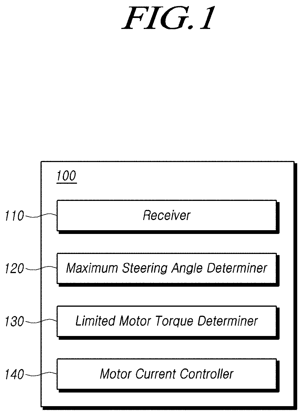
[0021]A steering auxiliary motor control device controls a steering assist motor or a steering auxiliary motor in the EPS system, and performs a funct...


PUM


Abstract

Disclosed are a steering auxiliary motor control device and a method thereof, the device comprising: a receiving unit for receiving steering angle information and driver steering torque information from a sensor included in a vehicle; a maximum steering angle determination unit for determining the maximum steering angle of the vehicle on the basis of the steering angle information and preset reference steering angle information; and a limited motor torque determination unit for determining limited motor torque for limiting maximum motor torque outputted from a steering auxiliary motor on the basis of a first condition including the steering angle information, the maximum steering angle information, and steering angle holding time information and/or a second condition including the driver steering torque information, over-torque limit entry torque information, over-torque limit release torque information, and steering torque holding time information.

Description

TECHNICAL FILED[0001]The present disclosure relates to a method and device for controlling a steering auxiliary motor in an EPS system, more particularly, related to a method and device for limiting the maximum torque of the steering auxiliary motor based on the steering angle information and the steering torque information to prevent over-torque of the steering auxiliary motor in the EPS system.BACKGROUND ART[0002]An electric power steering (EPS) system refers to a system that applies an auxiliary steering force to the driver's steering force using a motor. In order to assist the driver's steering force, a current is applied to a steering auxiliary motor or a steering assist motor to generate the auxiliary steering force.[0003]However, since the steering auxiliary motor used in the EPS system is a small and high-efficiency motor, a large amount of current flows along the coil inside the motor, and accordingly, there may be generated heat which is proportional to the winding resista...

Claims


Application Information

Patent Timeline
Patent Type & Authority Applications(United States)
IPC IPC(8): B62D6/00B62D15/02B62D5/04
CPCB62D6/002B62D5/0481B62D15/021B60W10/20B62D5/0469B62D6/10B62D5/0463B60W2510/202B60W2540/18
Inventor WON, JONGCHUN
Owner HL MANDO CORP
Why Eureka
Try Eureka