
Electronic time piece

a technology of electronic timepieces and timepieces, applied in the field of electronic timepieces, can solve the problems of large circuits and increased wire numbers

Pending Publication Date: 2022-03-03
CITIZEN WATCH CO LTD
View PDF0 Cites 0 Cited by
  • Summary
  • Abstract
  • Description
  • Claims
  • Application Information

AI Technical Summary

Benefits of technology

The objective of this invention is to offer an electronic time piece that can vary its appearance without making the circuits bigger. This is accomplished by using common modules.

Problems solved by technology

In such a configuration, the number of wires is increased, and the circuit tends to be large.

Method used


Image

  • Electronic time piece
  • Electronic time piece
  • Electronic time piece

Examples


first embodiment

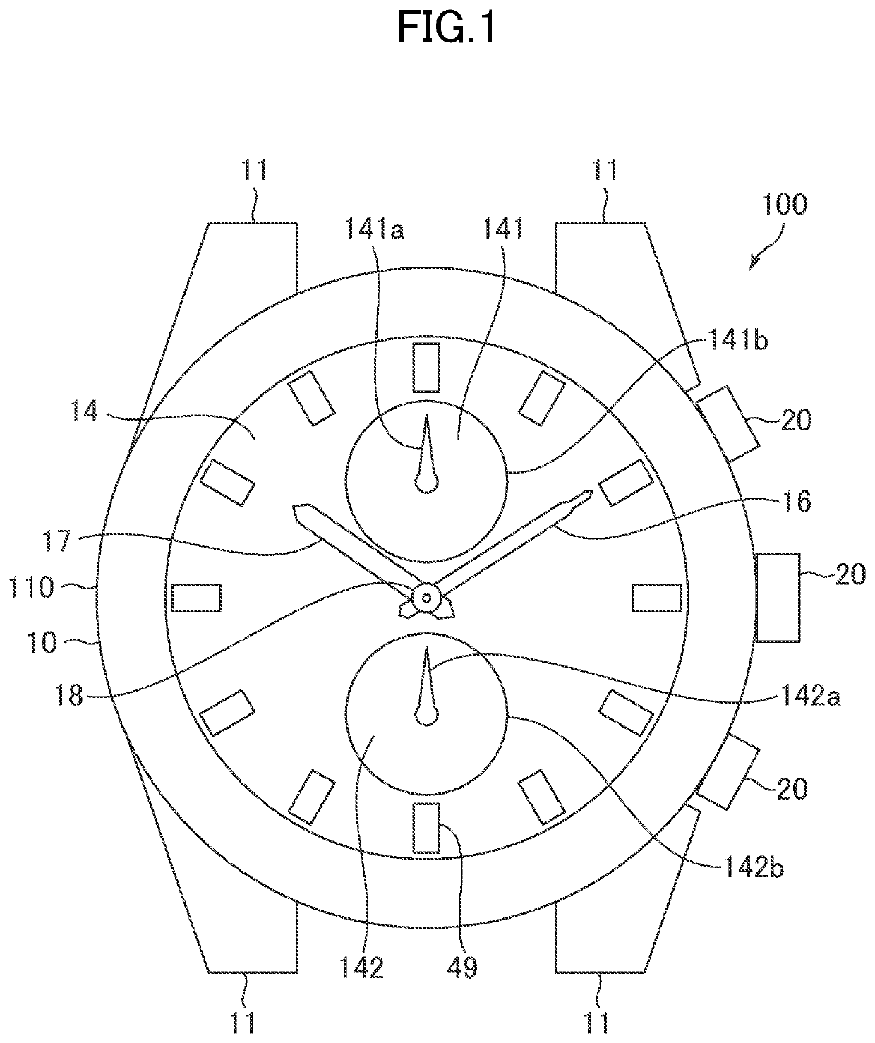
[0114]In the first embodiment, the movement 1 is housed in the outer case 10 at a disposing angle in which the mounting portion 21B of the main plate 2 is at the 3 o'clock position.

[0115]In the first embodiment, as shown in FIG. 9C, the terminal portion A corresponds to the first input unit 30a, the terminal portion B corresponds to the second input unit 30b, and the terminal portion C corresponds to the third input unit 30c. The function setting unit 30d sets a function to be executed when a switch signal is input to the first input unit 30a as the function 1, a function to be executed when a switch signal is input to the second input unit 30b as the function 2, and a function to be executed when a switch signal is input to the third input unit 30c as the function 3.

[0116]That is, the terminal portion A and the first input unit 30a are electrically connectable through the wire WA, and a switch signal is entered in the first input unit 30a in response to the user's operation of the ...

second embodiment

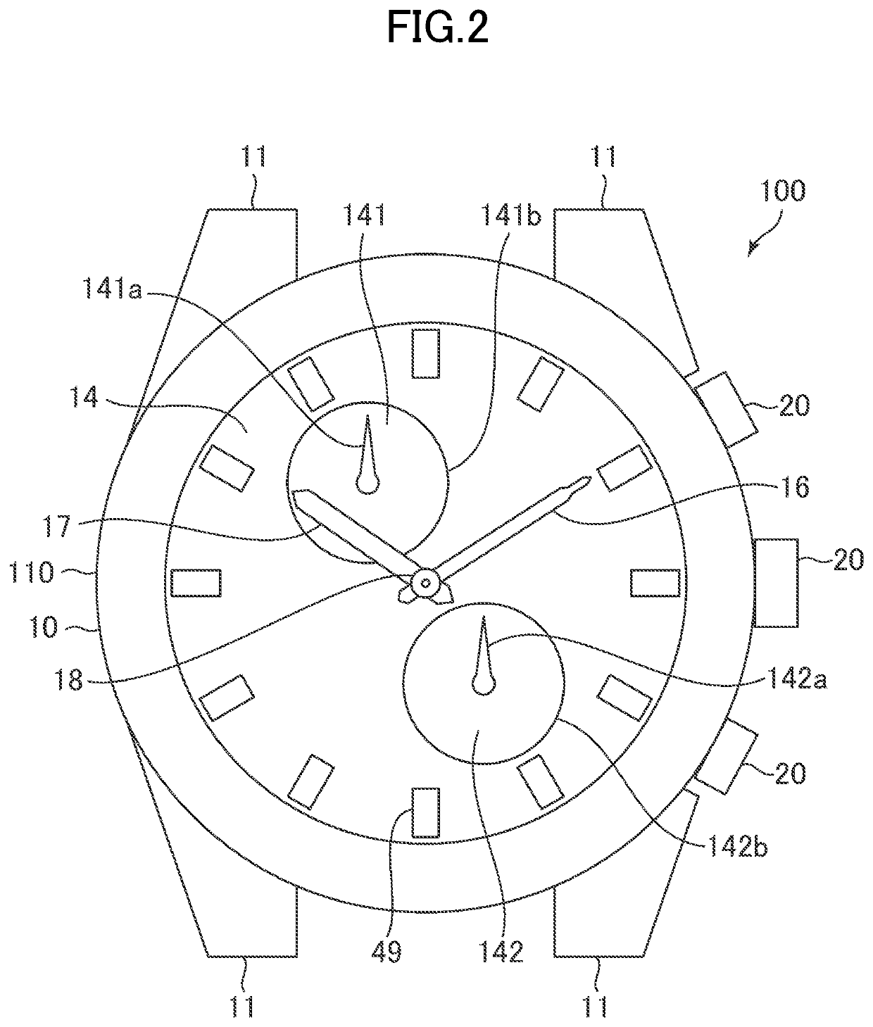
[0121]In the second embodiment, the movement 1 is housed in the outer case 10 at a disposing angle in which the mounting portion 21C of the main plate 2 is at the 3 o'clock position.

[0122]In the second embodiment, as shown in FIG. 10C, the terminal portion B corresponds to the second input unit 30b, the terminal portion C corresponds to the third input unit 30c, and the terminal portion D corresponds to the first input unit 30a. The function setting unit 30d sets a function to be executed when a switch signal is input to the second input unit 30b as the function 1, a function to be executed when a switch signal is input to the third input unit 30c as the function 2, and a function to be executed when a switch signal is input to the first input unit 30a as the function 3.

[0123]That is, the terminal portion B and the second input unit 30b are electrically connectable through the wire WB, and a switch signal is entered in the second input unit 30b in response to the user's operation of...

third embodiment

[0128]In the third embodiment, the movement 1 is housed in the outer case 10 at a disposing angle in which the mounting portion 21D of the main plate 2 is at the 3 o'clock position.

[0129]In the third embodiment, as shown in FIG. 11C, the terminal portion C corresponds to the third input unit 30c, the terminal portion D corresponds to the first input unit 30a, and the terminal portion E corresponds to the second input unit 30b. The function setting unit 30d sets a function to be executed when a switch signal is input to the third input unit 30c as the function 1, a function to be executed when a switch signal is input to the first input unit 30a as the function 2, and a function to be executed when a switch signal is input to the second input unit 30b as the function 3.

[0130]That is, the terminal portion C and the third input unit 30c are electrically connectable through the wire WC, and a switch signal is entered in the third input unit 30c in response to the user's operation of the...


PUM


Abstract

An electronic time piece includes a dial, a sub dial provided to the dial, a control circuit that controls operation of a function hand disposed on the sub dial, a plurality of terminal portions, a wire that electrically connects the plurality of terminal portions with the control circuit, a push button that receives operation by a user and switches an electrical connection state between one terminal portion of the plurality of terminal portions and the control circuit. The one terminal portion of the plurality of terminal portions and other terminal portion are electrically connected to the control circuit by a common wire.

Description

CROSS-REFERENCE TO RELATED APPLICATION[0001]The present application claims priority from Japanese application 2020-144787 filed on Aug. 28, 2020, the content of which is hereby incorporated by reference into this application.BACKGROUND OF THE INVENTION1. Field of the Invention[0002]The present invention relates to an electronic time piece.2. Description of the Related Art[0003]For example, JP2007-078504A discloses a wristwatch having a display unit provided on a dial and a plurality of buttons. The wristwatch of JP2007-078504A employs a configuration that does not require to manufacture the housing every time the layout of display unit is changed.[0004]The wristwatch of JP2007-078504A is required to provide wires for transmitting signals when the button is pressed to the control unit according to the number of terminal portions. In such a configuration, the number of wires is increased, and the circuit tends to be large.[0005]One or more embodiments of the present invention have bee...

Claims


Application Information

Patent Timeline
Patent Type & Authority Applications(United States)
IPC IPC(8): G04B19/06G04G19/00G04G21/00
CPCG04B19/06G04G21/00G04G19/00G04C3/005G04C3/146G04G17/06
Inventor MORITA, SHOICHIROKATO, AKIRA
Owner CITIZEN WATCH CO LTD
Learn More