
Non-volatile storage system compensating prior probability for low-density parity check codes

a non-volatile storage and parity check technology, applied in error detection/correction, instruments, coding, etc., can solve the problems of program-erase tolerance, two reliability problems, and the general sacrifice of the ability to increase the capacity of flash memory

Inactive Publication Date: 2014-05-06
HITACHI LTD
View PDF11 Cites 1 Cited by
  • Summary
  • Abstract
  • Description
  • Claims
  • Application Information

AI Technical Summary

Benefits of technology

This approach allows for accurate error correction with minimal deviation from actual error probabilities across multiple storage media, reducing circuit size and costs while maintaining correction capabilities, and is applicable to various nonvolatile storage systems.

Problems solved by technology

The widespread use of flash memory as a storage medium in computers is due to the short response time.
However, realizing increased capacity in flash memory generally involves sacrificing reliability.
Two problems exist with respect to reliability.
One problem relates to data retention characteristics.
One more problem is program-erase tolerance.
Writing (called programming) and deleting (called erasing) data to and from the flash memory damages the flash memory cell that stores the data.
However, in actuality, computing the posterior probability is not easy.
It is not possible to precisely compute the posterior log likelihood ratio function like this.
However, as described above, the bit error probability p of the flash memory cell increases as data programming is repeated.
Therefore, when the value of the prior probability (=bit error probability p) deviates from the actual value, the LDPC codes becomes incapable of correcting an error.

Method used


Image

  • Non-volatile storage system compensating prior probability for low-density parity check codes
  • Non-volatile storage system compensating prior probability for low-density parity check codes
  • Non-volatile storage system compensating prior probability for low-density parity check codes

Examples


example 1

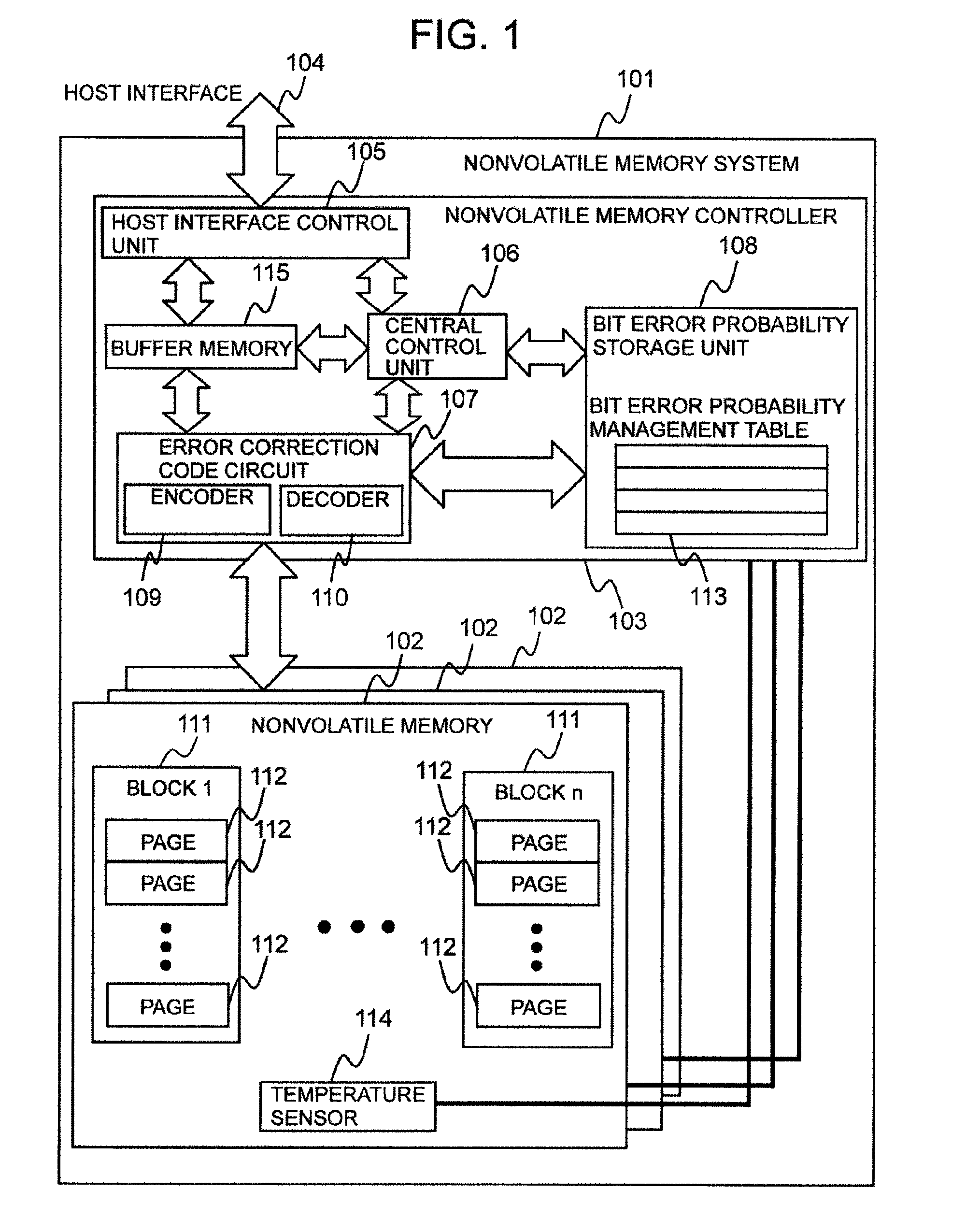
[0069]FIG. 1 shows a nonvolatile memory system related to a first example.

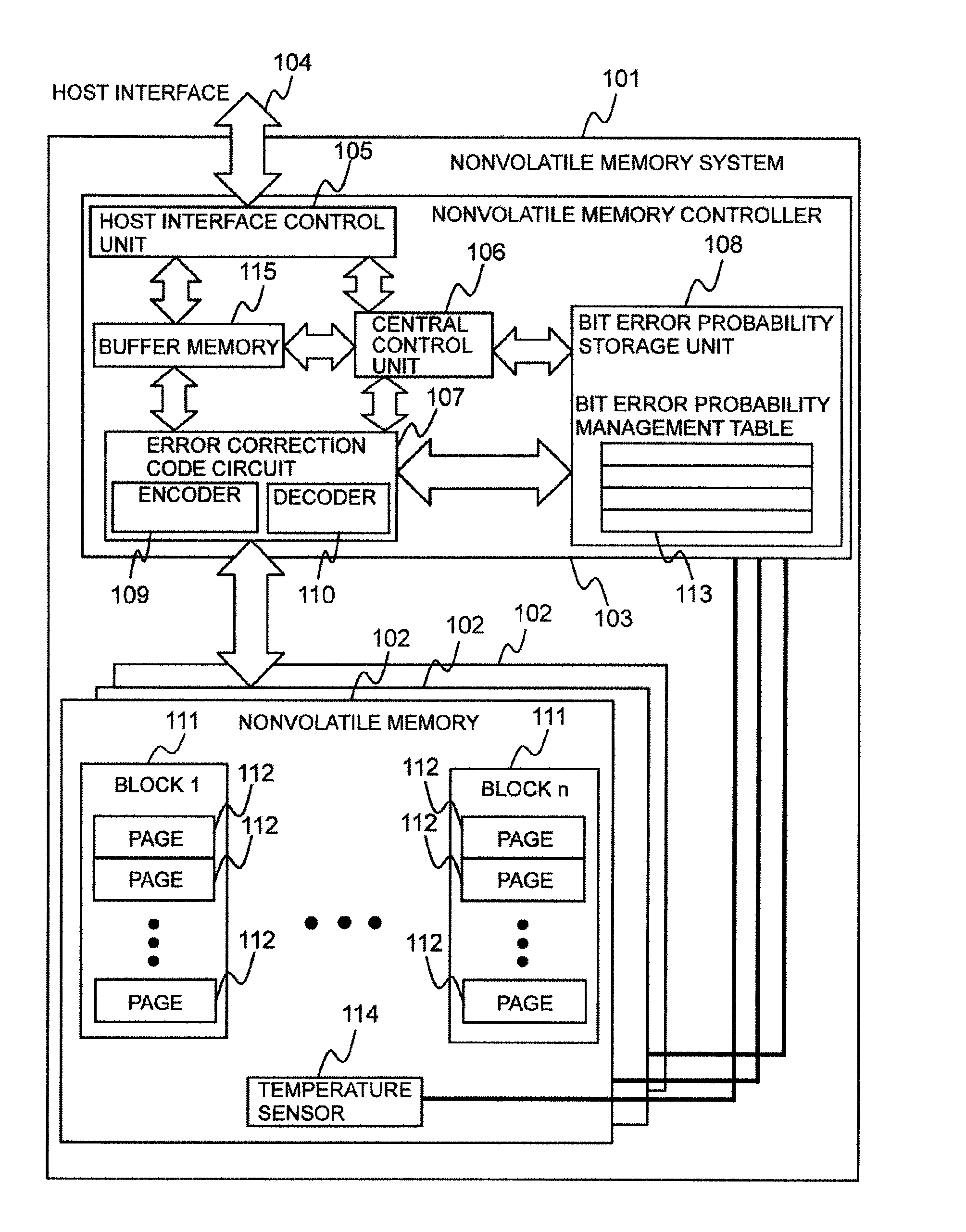
[0070]A nonvolatile memory system 101 comprises multiple (or one) nonvolatile memories 102, and a nonvolatile memory controller 103, which is coupled to the multiple non-volatile memories 102 and controls these memories 102. The nonvolatile memory controller 103 is coupled to a host (not shown in the drawing) by way of a host interface 104. The host (not shown in the drawing) sends a data input / output command to the nonvolatile memory controller 103, and the nonvolatile memory controller 103 executes the input / output of the data to / from the nonvolatile memory 102 in accordance with this command.

[0071]The nonvolatile memory controller 103 comprises a host interface control unit 105 for controlling the host interface 104, an error correcting code circuit 107 for encoding / decoding data, a bit error probability storage unit 108 for storing a bit error probability, a central control unit 106, and a buffer memory 11...

example 2

[0099]A second example will be explained below. In so doing, the differences with the first example will mainly be explained, and explanations of the points in common with the first example will either be simplified or omitted.

[0100]The bit error probability of the flash memory is affected by the elapsed time from when data is programmed until the data is read (hereinafter, the PR elapsed time), for example, is proportional to the PR elapsed time. That is, when it is supposed that the PR elapsed time is t, the bit error probability is expressed using math (18).

p(t)=a0t+p0  [Math.18]

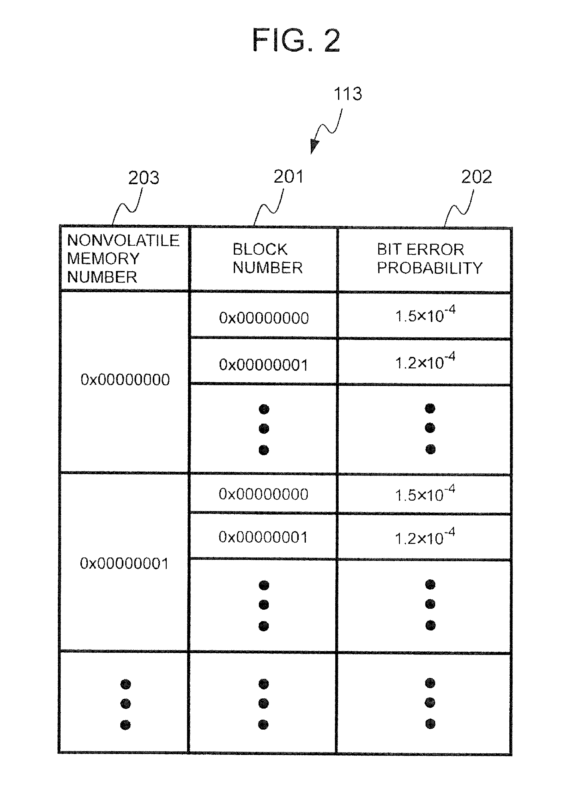
[0101]The a0 is a proportionality coefficient, and the p0 is an intercept. In a case where the nonvolatile memory 102 is managed in units of blocks, the bit error probability management table 113 stores the time at which the data was last programmed, the proportionality coefficient, and the intercept for each block. Numerical values obtained by experiment may be used as the initial values of the numerical...

example 3

[0134]A third example will be explained below. In so doing, the points of difference with the first example and / or the second example will mainly be explained, and explanations of the points in common with the first example and / or the second example will be simplified or omitted.

[0135]In this example, the flash memory bit error probability is decided on the basis of a number of programmings, a number of reads, and a temperature.

[0136]Programming data to a page (to include erasing) causes damage to the flash memory cell(s) inside this page and an increase in the bit error probability of this page.

[0137]Reading data from a page also causes an increase in the bit error probability of this page. This is referred to as a read disturb. When data is read from a flash memory, electrons are discharged to a small extent from the flash memory cell where the electrons are stored. In a flash memory, the distinction between the information 0 and 1 is made in accordance with states in which electr...


PUM


Abstract

Provided in one embodiment is a nonvolatile storage system having multiple nonvolatile storage media and a controller coupled to the multiple nonvolatile storage media. The controller has a storage area configured to store management information including probability management information denoting error probability information of a unit physical area in a nonvolatile storage medium, and an error correcting circuit configured to carry out coding and decoding by a low density parity check code. The controller, in a data read process, is configured to identify based on management information an error probability, uses the identified error probability to correct the read data using the error correcting circuit.

Description

TECHNICAL FIELD[0001]The present invention relates to information storage systems which have error correction function by means of low-density parity check codes.BACKGROUND ART[0002]Efforts to increase the capacity of NAND-type flash memory (hereinafter called flash memory) have progressed in recent years, and flash memory has come to be used in place of a hard disk drive (hereinafter HDD) as a secondary storage system. For example, whereas the response time of the HDD is roughly 10 milliseconds, the response time of the flash memory, for example, is roughly between 100 microseconds and 2 milliseconds, making it extremely shorter than that of the HDD. The widespread use of flash memory as a storage medium in computers is due to the short response time.[0003]However, realizing increased capacity in flash memory generally involves sacrificing reliability. Two problems exist with respect to reliability.[0004]One problem relates to data retention characteristics. In a typical flash memo...

Claims


Application Information

Patent Timeline
Patent Type & Authority Patents(United States)
IPC IPC(8): G11C29/00H03M13/00G06F11/00
CPCG06F11/108G06F11/1068
Inventor HASHIMOTO, AKIYOSHISUZUKI, AKIFUMITSUNEHIRO, TAKASHI
Owner HITACHI LTD
Learn More