
PSK receiver, PSK demodulating circuit, communication apparatus, and PSK receiving method

a demodulating circuit and receiver technology, applied in the field of psk receivers, psk demodulating circuits, communication apparatus, and psk receiving methods, can solve the problems of increasing accelerating the increase in the size of the circuit, so as to reduce the demodulation error caused by phase rotation, not increase the circuit size

Inactive Publication Date: 2010-06-01
138 EAST LCD ADVANCEMENTS LTD
View PDF5 Cites 5 Cited by
  • Summary
  • Abstract
  • Description
  • Claims
  • Application Information

AI Technical Summary

Benefits of technology

"The invention provides a phase-shift keying (PSK) receiver, demodulator, and communication apparatus that can demodulate a phase-modulated signal without increasing the size of the circuit. The receiver uses a binary phase-shift keying (BPSK) scheme on the basis of positional relation on an I-Q constellation of 1-bit digital signals corresponding to an in-phase component and a quadrature component of the received signal. The receiver can reduce demodulation error caused by phase rotation and can determine the phase points without needing a multi-bit analog-to-digital converter or a large-capacity random-access memory. The receiver can also determine the phase points by dividing the I-Q constellation into different domains and analyzing the signals within those domains. Overall, the invention provides a more efficient and compact solution for demodulating phase-modulated signals."

Problems solved by technology

The complex multiplication requires four multipliers, which increases the size of the circuit.
The calculation requires a large-capacity ROM, which increases the size of the circuit.
Moreover, in the described methods, the phase compensation operation requires a multi-bit AD converter, which accelerates the increase in the size of the circuit.
Consequently, it is unnecessary to perform bothersome calculation in order to obtain the phase θ from the in-phase component I and the quadrature component Q of the received signal, and the size of the circuit is not increased.

Method used


Image

  • PSK receiver, PSK demodulating circuit, communication apparatus, and PSK receiving method
  • PSK receiver, PSK demodulating circuit, communication apparatus, and PSK receiving method
  • PSK receiver, PSK demodulating circuit, communication apparatus, and PSK receiving method

Examples


first embodiment

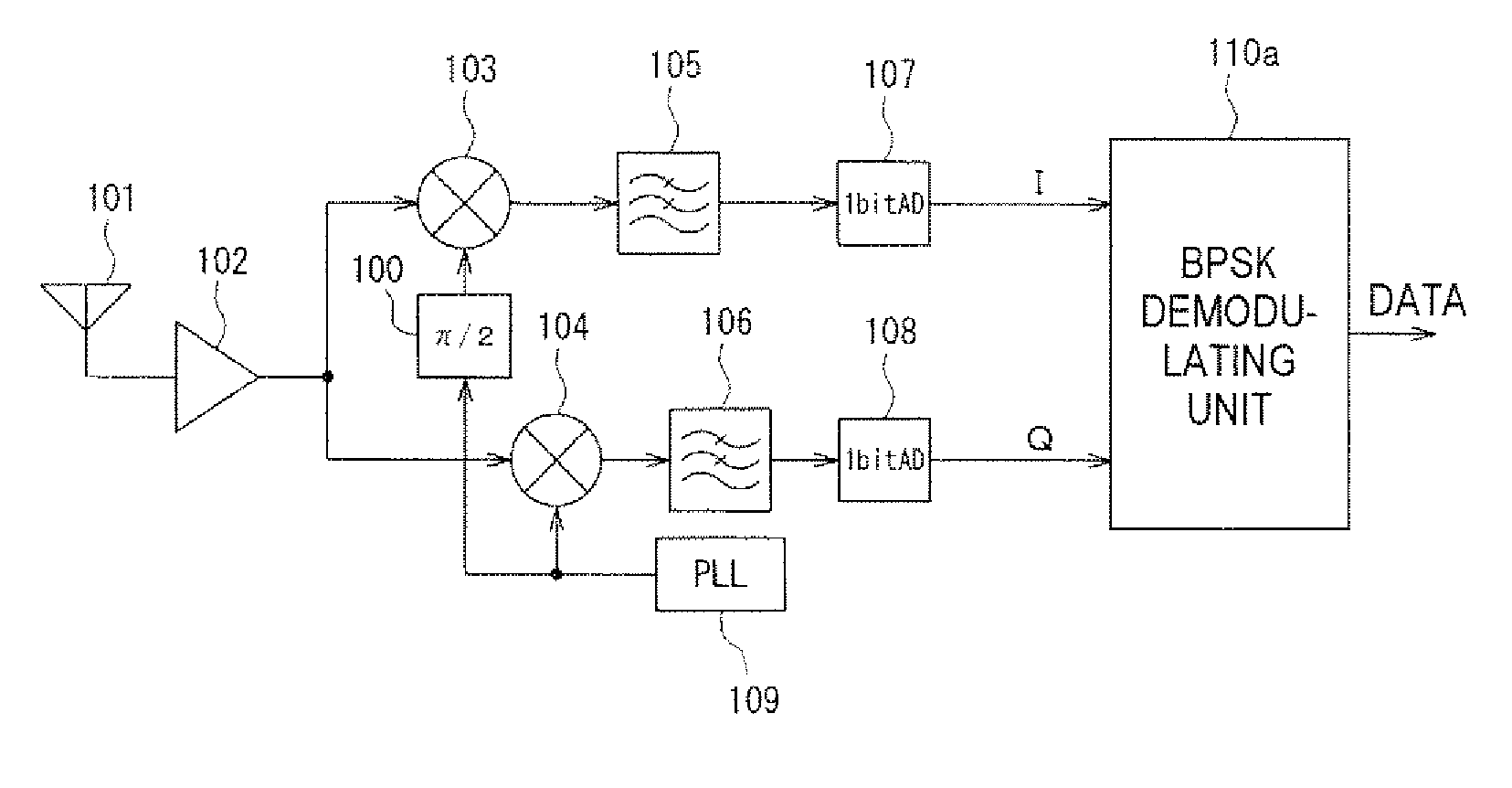
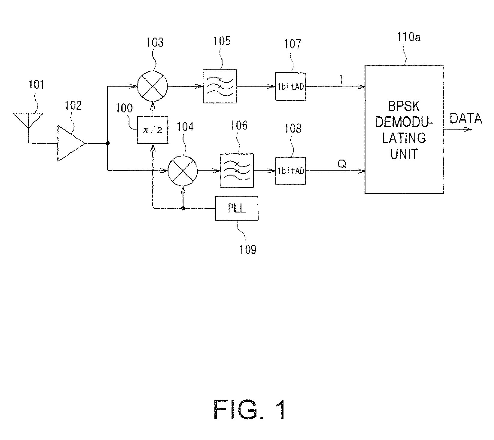
[0057]FIG. 1 is a block diagram illustrating a BPSK receiver according to the invention.

[0058]In FIG. 1, a radio receiver includes an antenna 101 that receives quadrature modulated radio wave, a low noise amplifier 102 that receives from the antenna 101 and amplifies a received signal, a PLL circuit 109, a phase shifter 100 that shifts phase of a generated carrier wave in the PLL circuit 109 by π / 2, a mixer 103 that extracts an in-phase component I of the received signal by mixing the carrier wave whose phase is shifted by π / 2 and a amplified received signal in the low noise amplifier 102, a mix 104 that extracts a quadrature component Q of the received signal by mixing the carrier wave generated in the PLL circuit 109 and the amplified received signal in the low noise amplifier 102, a low-pass filter 105 that eliminates unnecessary high-pass components from the generated signal from the mixer 103, a low-pass filter 106 that eliminates the unnecessary high-pass components from a gen...


PUM


Abstract

A phase-shift keying (PSK) receiver includes a carrier wave generator generating a carrier wave, an extracting unit extracting an in-phase component I and a quadrature component Q from a received signal on the basis of the carrier wave and the received signal, a comparator comparing the in-phase component I and the quadrature component Q extracted from the received signal to a predetermined threshold values respectively and acquiring 1-bit digital signals corresponding to the in-phase component I and the quadrature component Q respectively; and a BPSK demodulator demodulating the received signal using a binary phase-shift keying (BPSK) scheme on the basis of positional relationship on I-Q constellation between the 1-bit digital signals corresponding to the in-phase component I and the quadrature component Q acquired by the comparator.

Description

BACKGROUND[0001]1. Technical Field[0002]The present invention relates to a phase-shift keying (PSK) receiver, a PSK demodulating circuit, a communication apparatus, and a PSK receiving method, and more particularly, to a phase-shift keying (PSK) receiver, a PSK demodulating circuit, a communication apparatus, and a PSK receiving method, suitable for application to a technology in which a demodulation operation is performed on the basis of an in-phase component I and a quadrature component Q which are converted into a 1-bit digital signal.[0003]2. Related Art[0004]As a semi-synchronous detection method in the PSK demodulation, there are a method in which a carrier wave is synchronized on the basis of the received in-phase component I and the quadrature component Q (JP-A-2001-024726) and a method in which a carrier wave is synchronized on the basis of a phase θ obtained by applying the following formula (1) to the received in-phase component I and the quadrature component Q (JP-A-9-11...

Claims


Application Information

Patent Timeline
Patent Type & Authority Patents(United States)
IPC IPC(8): H04L27/22
CPCH04L27/227H04L25/062H04L7/0331H04L2027/0028H04L27/22H04L27/32H04L27/38
Inventor MIZUKAMI, HIROMITSU
Owner 138 EAST LCD ADVANCEMENTS LTD
Learn More