Boring tool

a boring tool and spring technology, applied in the field of boring tools, can solve the problems of high undesirable, expensive, complicated and not so reliable, and the manual adjustment of boring tools is considered time-consuming and therefore highly undesirable, and achieves the effect of sufficient biasing force from the spring

Pending Publication Date: 2022-03-10
SANDVIK COROMANT
View PDF8 Cites 0 Cited by
  • Summary
  • Abstract
  • Description
  • Claims
  • Application Information

AI Technical Summary

Benefits of technology

[0012]Thus, when the drive unit is operated to move the clamping member towards the locked position, the spring acts to press a first set of flanks of the threads together, i.e. the flanks of the bolt thread that face the spring and the flanks of the recess thread that face away from the spring. If the drive unit is allowed to continue to operate and to turn the bolt thread in the recess thread after the clamping member has reached the locked position, a second set of flanks of the threads will engage and press against each other. This second set of flanks include the flanks of the bolt thread that face away from the spring and the flanks of the recess thread that face the spring. Therein eventually the force between the second set of flanks may correspond to a desired clamping force between the clamping member and slider member. However, advantageously, when the clamping member has reached the locked position, the drive unit does not have to provide a force to the bolt in order for the clamping member to remain in the locked position and to ensure a defined clamping force. In other words, the flanks of the bolt thread do not have to be pressed against the corresponding flanks of the recess thread in order to apply a clamping force to the slider member. Instead, the biasing force from the spring is sufficient. Thus, in the locked position, the clamping force is provided by the biasing force from the spring and the drive unit can be turned off. In embodiments where there is a play between the flanks of the threads, the flanks can be disengaged in the locked position.

Problems solved by technology

In environments where there are high demands for productivity manual adjustment of boring tools is considered time consuming and therefore highly undesirable.
A problem with piezoelectric elements is that they are expensive, complicated and not so reliable.

Method used


Image

  • Boring tool
  • Boring tool

Examples


Embodiment Construction

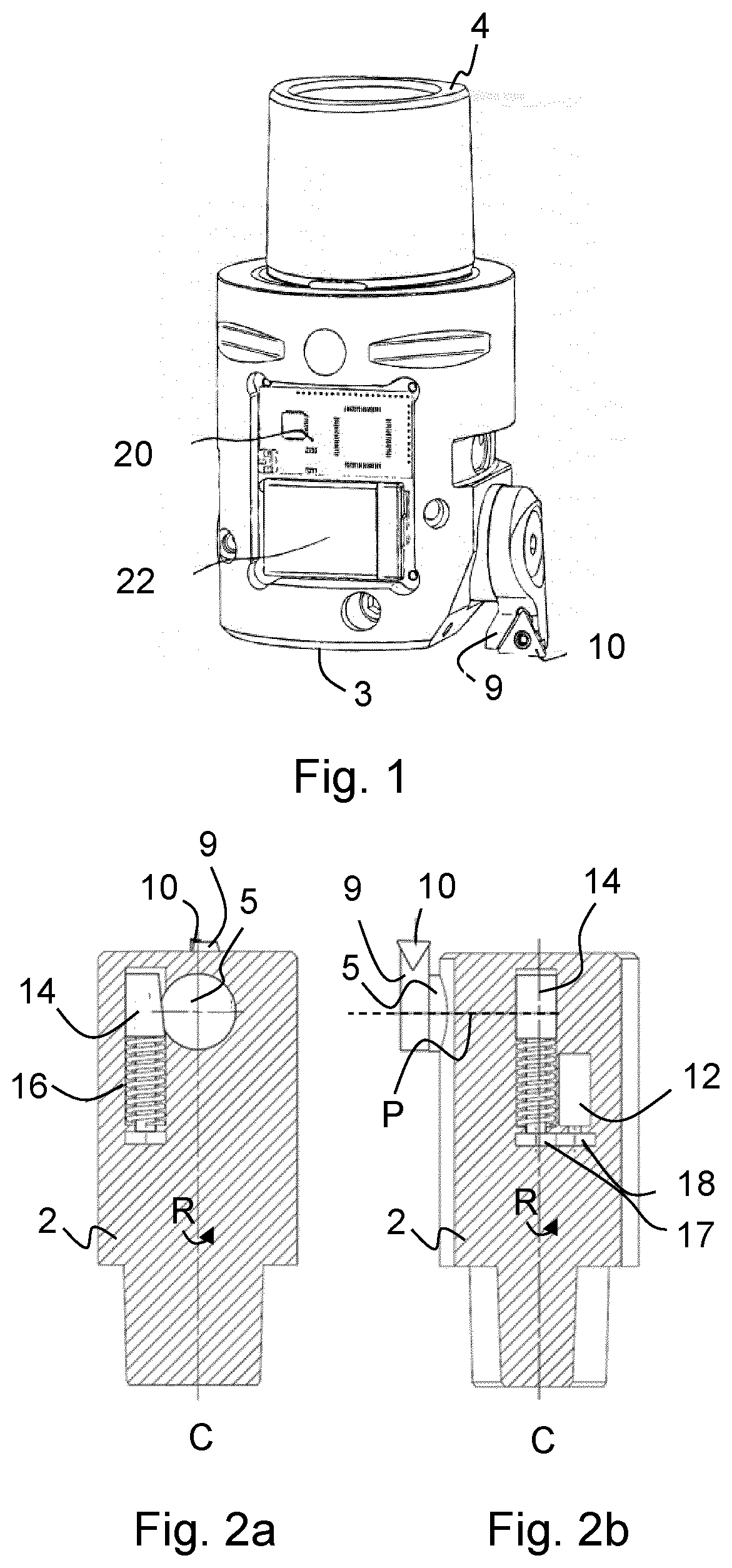
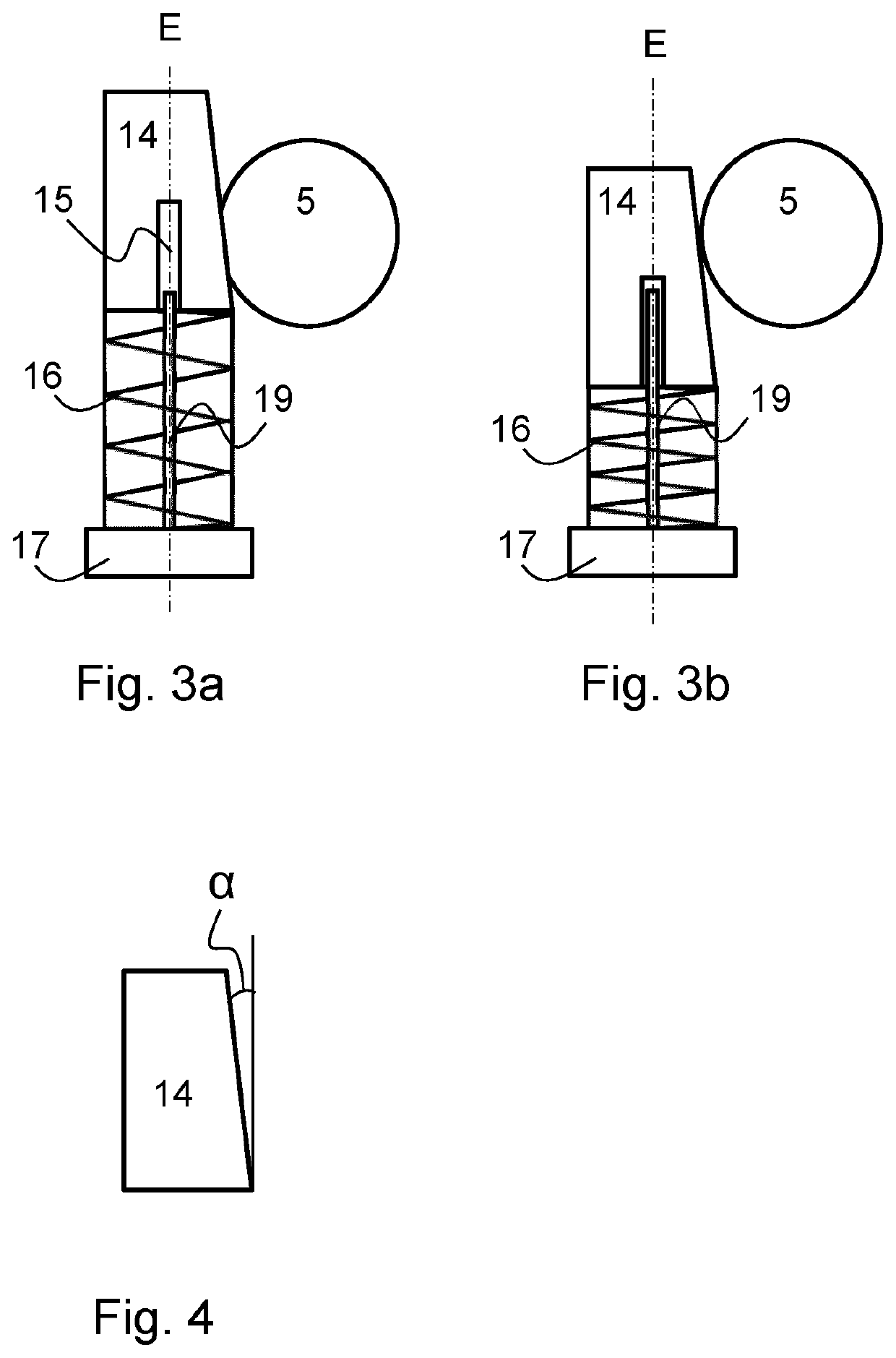
[0021]In the following, a detailed description of a boring tool according to the present invention will be made. In context of the present disclosure a boring tool is to be interpreted broadly may be used by for metal cutting, for chip removing machines and machine processes for enlarging an already existing hole. Reference will now be made in parallel to FIG. 1, FIGS. 2a and 2b and FIGS. 3a and 3b when describing the boring tool. The same reference numerals will be used for denoting the same feature in all figures. The boring tool has a tool body 2 including a front end 3 and a rear end 4, between which a central rotation axis C extends around which the tool body 2 is rotatable in a direction of rotation R. The boring tool further comprises a slider member 5, a cutting insert seat 9, a drive unit 12, a wedge-shaped clamping device 14, a biasing spring 16, a gear arrangement comprising a first gear wheel 17 and a second gear wheel 18 and a threaded bolt 19.

[0022]The slider member 5 ...


PUM


Abstract

A boring tool has a slider member connected to a cutting insert seat, the slider member is arranged movably inside a tool body of the boring tool along a path extending transversely to a rotation axis of the boring tool for adjusting the distance of the of the cutting insert seat in relation to the rotation axis. A wedge-shaped clamping member is connected to a drive unit and arranged inside the tool body. The wedge-shaped clamping member is in contact with the slider member for clamping the slider member into a locked position, in which locked position, the wedge-shaped clamping member is pre-loaded to passively lock the slider member. The drive unit is controllable such that the wedge-shaped clamping member is actively releasable when adjusting the distance of the cutting insert seat.

Description

TECHNICAL FIELD[0001]The present invention relates generally to a boring tool and especially a boring tool in which a seat for holding a cutting insert is movable in relation to a rotation axis of the boring tool, such that the cutting diameter of the boring tool may be adjusted.BACKGROUND[0002]A boring tool is typically used for enlarging an already existing hole by means of rotating a tool body provided with one or more cutting inserts. The process is commonly performed in order to achieve accurate dimensions, tight tolerances or a certain surface finish. Typical boring tool bodies are often supplied with a radially adjustable cutting edge that enables a variable cutting diameter as well as the possibility to compensate for wear of the cutting insert.[0003]Traditionally, the adjustment of the cutting diameter is done manually by the machine operator, through e.g. turning an adjustment screw on the tool body. In environments where there are high demands for productivity manual adju...

Claims


Application Information

Patent Timeline
Patent Type & Authority Applications(United States)
IPC IPC(8): B23B29/034
CPCB23B29/03403B23B2260/146
Inventor FRANK, PETERLIEBAUG, CHRISTIAN
Owner SANDVIK COROMANT
Why Eureka
Try Eureka