Power steering apparatus and backlash adjustment mechanism therefor

a technology of backlash adjustment and power steering, which is applied in mechanical devices, transportation and packaging, hoisting equipment, etc., can solve the problems of insufficient biasing force of annular elastic bodies, inability to maintain sufficient biasing force, and insufficient reduction of backlash between gear teeth of worm shafts and gear teeth, so as to reduce backlash, reduce backlash, and deepen the engagement of gear teeth

Active Publication Date: 2016-03-10
HITACHI ASTEMO LTD
View PDF1 Cites 14 Cited by
  • Summary
  • Abstract
  • Description
  • Claims
  • Application Information

AI Technical Summary

Benefits of technology

[0004]Herein, there is a possibility that the gear teeth of the worm wheel will wear during use. The above conventional power steering apparatus allows, when the distance between the gear teeth of the worm wheel and the worm shaft increases with wearing of the gear teeth of the worm wheel, the annular elastic body to move the worm shaft in a direction that deepens the engagement of the gear teeth of the worm shaft with the gear teeth of the worm wheel and reduces the backlash between the gear teeth of the worm shaft and the gear teeth of the worm wheel. By such movement, however, the annular elastic body returns close to its original shape so that the elastic force of the annular elastic body decreases with the amount of deformation. The annular elastic body may thus become unable to maintain its sufficient biasing force against the worm shaft and, when the wearing of the gear teeth of the worm wheel further proceeds, fail to adequately reduce the backlash between the gear teeth of the worm shaft and the gear teeth of the worm wheel. This leads to deterioration of gear transmission performance, occurrence of noise by gear teeth collision (called “gear teeth hitting noise”) and the like.

Problems solved by technology

Herein, there is a possibility that the gear teeth of the worm wheel will wear during use.
The annular elastic body may thus become unable to maintain its sufficient biasing force against the worm shaft and, when the wearing of the gear teeth of the worm wheel further proceeds, fail to adequately reduce the backlash between the gear teeth of the worm shaft and the gear teeth of the worm wheel.
This leads to deterioration of gear transmission performance, occurrence of noise by gear teeth collision (called “gear teeth hitting noise”) and the like.

Method used


Image

  • Power steering apparatus and backlash adjustment mechanism therefor
  • Power steering apparatus and backlash adjustment mechanism therefor
  • Power steering apparatus and backlash adjustment mechanism therefor

Examples


first embodiment

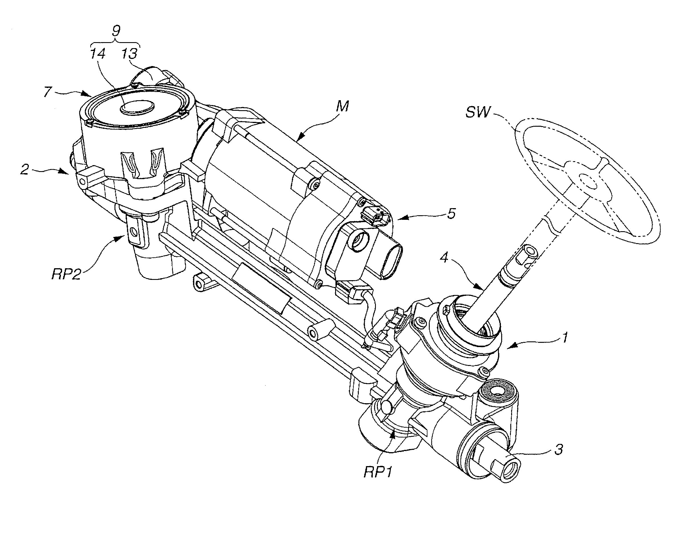
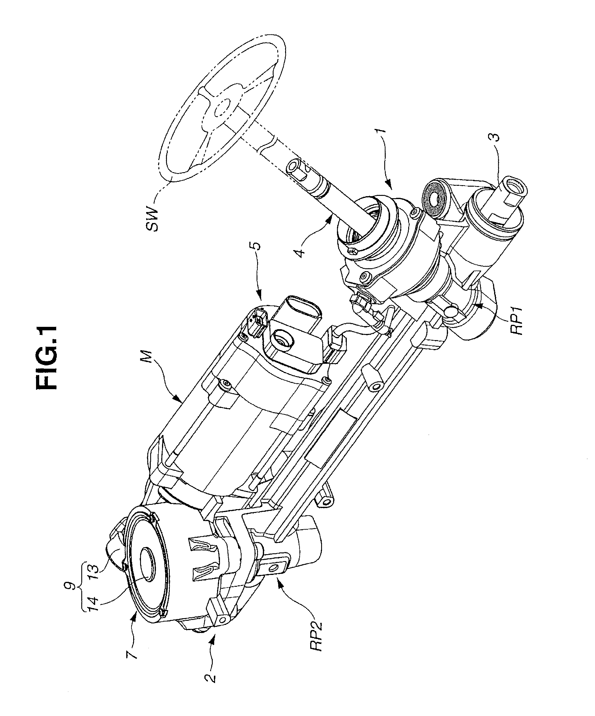
[0021]As shown in FIG. 1, the power steering apparatus is designed as a so-called dual pinion type electric power steering apparatus, including a steering mechanism with a rack-and-pinion steering system 1 and a rack-and-pinion steering assist system 2. The rack-and-pinion steering system 1 is connected to a steering wheel SW and adapted to transmit a driver's steering force from the steering wheel SW to steerable vehicle wheels (not shown). The rack-and-pinion steering assist system 2 is connected to an electric motor M and adapted to transmit a rotational force of the electric motor M as a steering assist force to the steerable vehicle wheels. Both of the rack-and-pinion steering system 1 and the rack-and-pinion steering assist system 2 are disposed on a common rack bar 3. Although not specifically shown in the drawings, both end portions of the rack bar 3 are connected to the steerable vehicle wheels through tie rods and knuckle anus, respectively. The power steering apparatus al...

second embodiment

[0076]The power steering apparatus of the second embodiment is structurally similar to that of the first embodiment as shown in FIG. 7, except for the shapes of the first and second sliding surfaces 30 and 40.

[0077]More specifically, the first and second sliding surfaces 30 and 40 are stepped (e.g. notched) in shape as shown in FIG. 8 in the second embodiment.

[0078]The first sliding surface 30 has a plurality of first contact regions 42 aligned substantially in parallel with the movement direction of the slider 37 and a plurality of step regions connecting the first contact regions 42. By these regions, the first sliding surface 30 is inclined in a stepwise shape with respect to the movement direction of the slider 37.

[0079]Similarly, the second sliding surface 40 has a plurality of second contact regions 43 aligned substantially in parallel and brought into engagement with the first contact regions 42 and a plurality of step regions connecting the second contact regions 43. By thes...

third embodiment

[0086]The power steering apparatus of the third embodiment is structurally similar to that of the first embodiment, except for the structure and operation of the slider 37.

[0087]More specifically, the slider 37 is arranged to move circumferentially about the rotation axis of the worm shaft 11, rather than to move linearly, as shown in FIGS. 9 and 10 in the third embodiment.

[0088]The backlash adjustment mechanism further includes a bottomed cylindrical casing 44 press-fitted in the opening 13c of the shaft accommodation part 13.

[0089]The slider unit 22 is disposed between the bearing unit 21 and the casing 44. In the sliding unit 22, the slider 39 is formed into a curved wedge shape along the circumferential direction of the worm shaft 11 such that the thickness of the slider 37 gradually decrease in the clockwise direction from the backward end portion 37a to the forward end portion 37b. Thus, an inner circumferential end surface of the slider 37 as a whole (facing the bearing unit ...


PUM


Abstract

A power steering apparatus includes a worm gear that transmits a rotational force of an electric motor to a steering mechanism through engagement of a worm shaft and a worm wheel and a backlash adjustment mechanism that reduces backlash between the worm shaft and the worm wheel. The backlash adjustment mechanism has a ball bearing mounted to the worm shaft, a slider movable in a movement direction substantially perpendicular to a rotation axis of the worm shaft, a first sliding surface provided on an outer circumferential side of an outer race of the ball bearing, and a second sliding surface provided on the slider and brought in sliding contact with the first sliding surface such that forward movement of the slider in the movement direction causes relative sliding of the first and second sliding surfaces to bring the worm shaft closer to the worm wheel.

Description

BACKGROUND OF THE INVENTION[0001]The present invention relates to a power steering apparatus and, more particularly, to a backlash adjustment mechanism arranged in the power steering apparatus to reduce backlash in a worm gear.[0002]Japanese Laid-Open Patent Publication No. 2004-345444 discloses a conventional type of power steering apparatus that includes a steering mechanism for transmitting a driver's steering force to steerable wheels, an electric motor for applying a torque as a steering assist force and a worm gear for transmitting the torque of the electric motor to the steering mechanism. The worm gear has, in a gear housing, a worm shaft rotatably mounted on a ball bearing and a worn wheel engaged with the worm shaft so as to reduce the motor torque and transmit the reduced motor torque to the steering mechanism.[0003]This power steering apparatus further includes an annular elastic body disposed on the worm gear as a backlash adjustment mechanism. The annular elastic body ...

Claims


Application Information

Patent Timeline
Patent Type & Authority Applications(United States)
IPC IPC(8): B62D7/22B62D5/04F16H55/24
CPCB62D7/226F16H55/24B62D5/0454B62D5/0445B62D5/24B62D5/0424B62D5/0409
Inventor KIMOTO, SUSUMU
Owner HITACHI ASTEMO LTD
Why Eureka
Try Eureka