Hand railings

a technology of hand railings and railings, which is applied in the direction of balusters, building types, constructions, etc., can solve the problems of reducing the yield, reducing the yield, and disadvantages of conventional railing structures, and achieves even stronger engagement between metal rods and plastic covers, and the effect of increasing the manufacturing yield

Active Publication Date: 2016-02-23
LI JIA HAO
View PDF22 Cites 1 Cited by
  • Summary
  • Abstract
  • Description
  • Claims
  • Application Information

AI Technical Summary

Benefits of technology

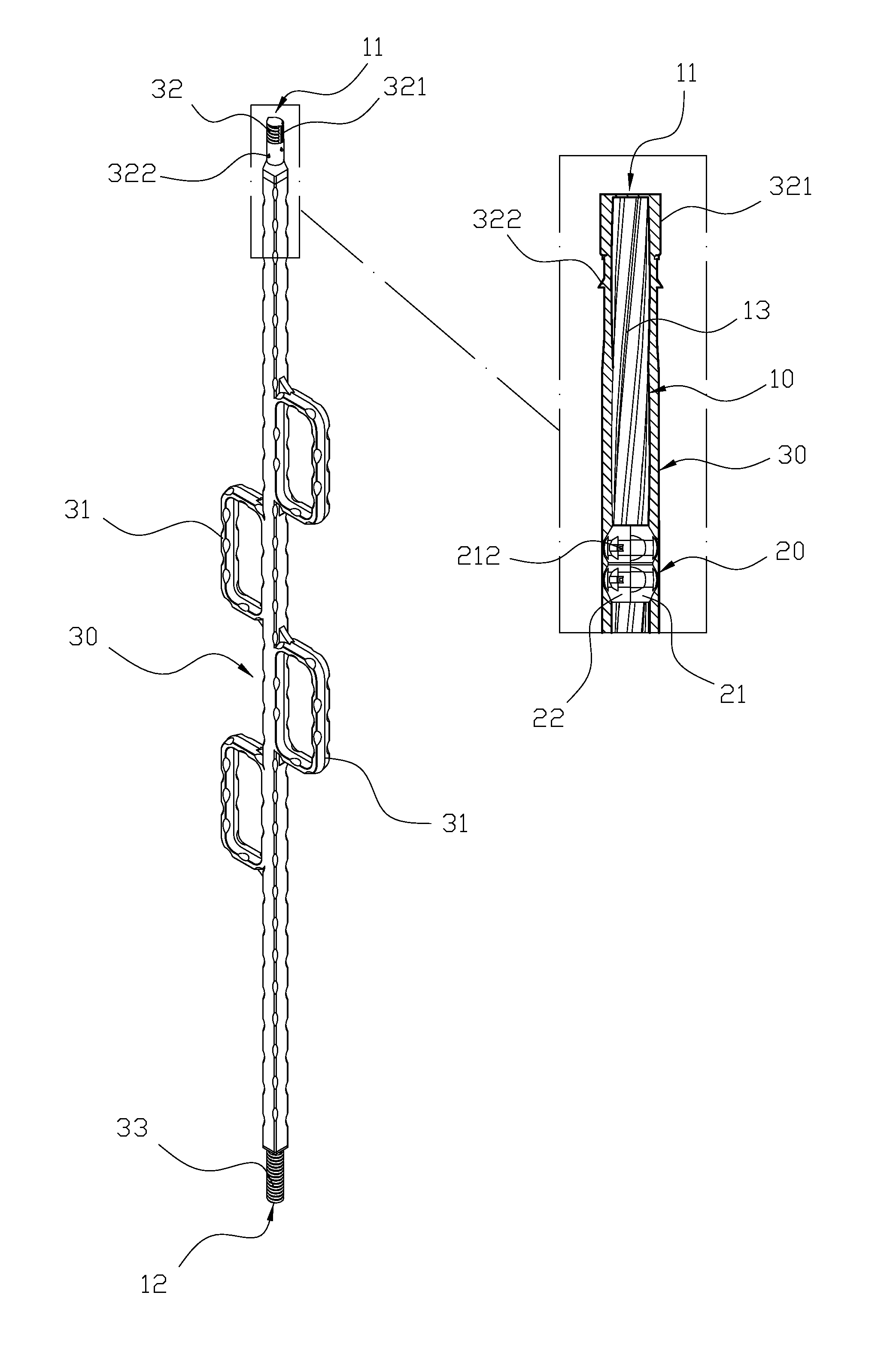
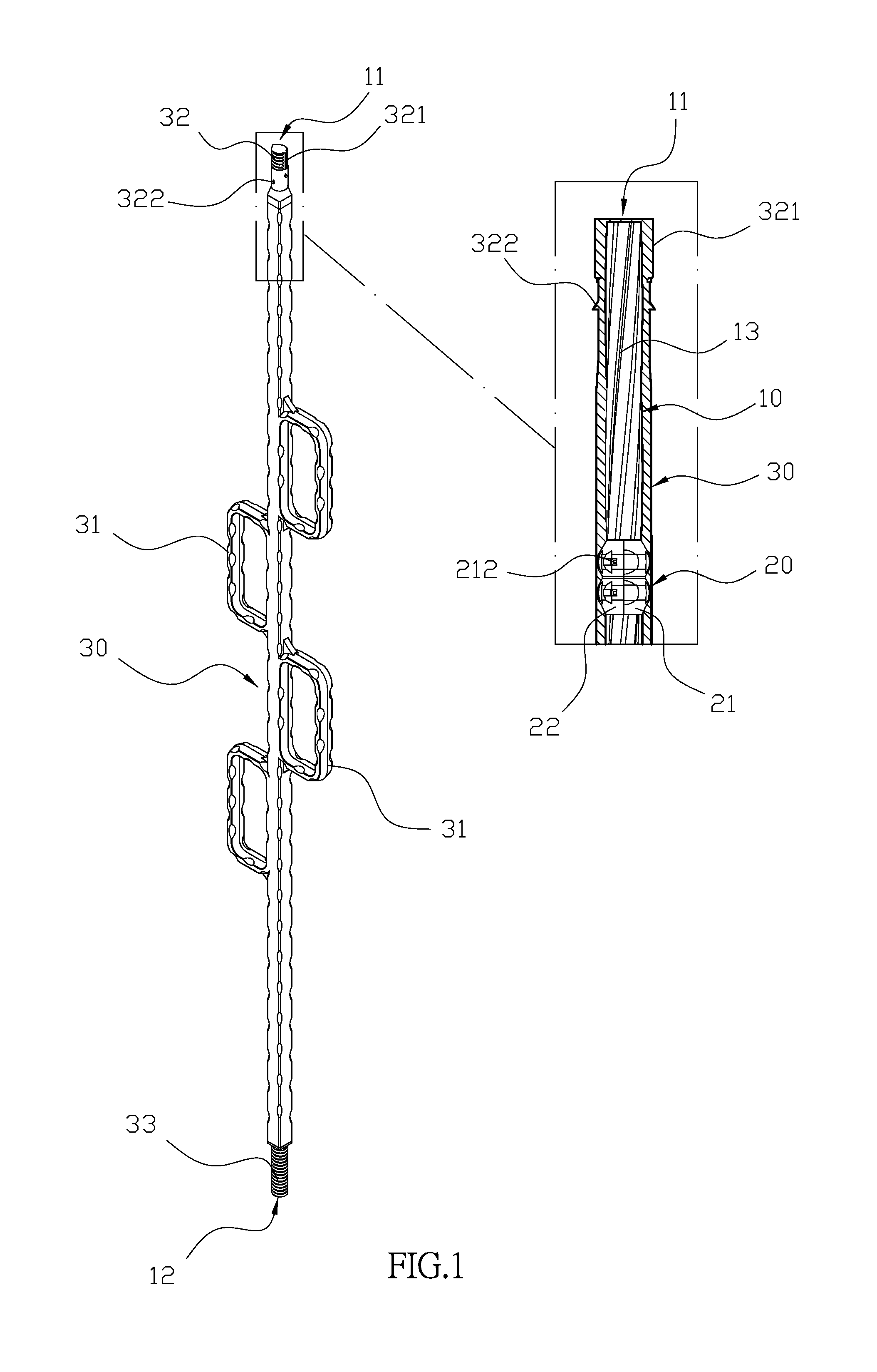
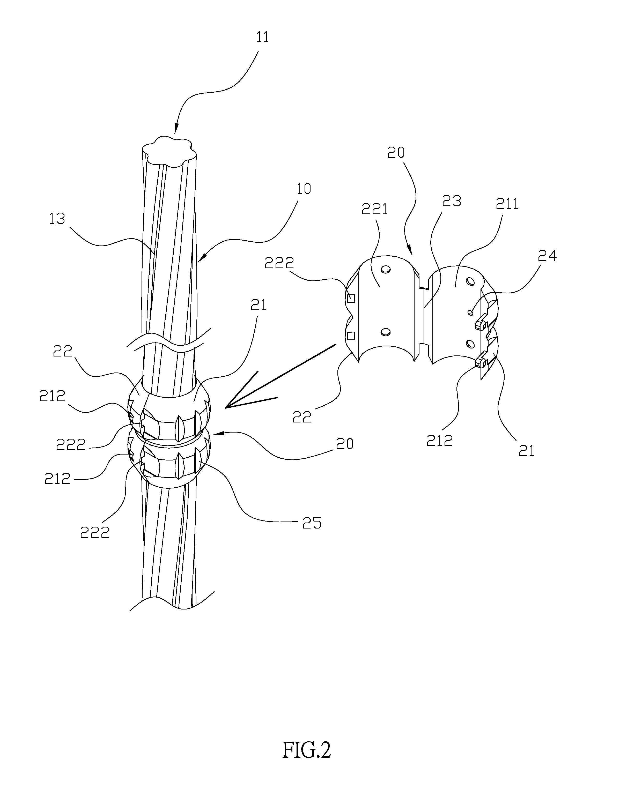
[0009]Comparing with conventional hand railings, the present invention is advantageous because the connecting portion is used to open up the cover bodies, and the arc surfaces cover the surface of the metal rod, so the reverse hook portion and fixed hole are engaged so the positioning units are secured on the surface of the metal rod. The metal rod is then placed in the injection mold, and the positioning unit is disposed between the metal rod and injection mold. Meanwhile, the melted plastic cover is introduced into the mold to fill the mold including the recessed portions and melt the surface of the positioning unit, so the plastic cover can completely cover the metal rod and the positioning unit. Furthermore, since the melted plastic cover also flows into recessed slot, the engagement between the metal rod and plastic cover is even stronger. The manufacturing yield can also be increased because of the positioning units.

Problems solved by technology

However, conventional railing structure is disadvantageous because during the manufacturing process, the metal rod 61 is disposed in the molding directly and secured only at two ends thereof, so the metal rod 61 is not secured at the center portion of the molding.
Also, when the metal rod 61 is in contact with the molding, the plastic cannot cover the contacted area of the metal rod 61, which would lead to a bad product and reduce the yield.

Method used


Image

  • Hand railings
  • Hand railings
  • Hand railings

Examples


Embodiment Construction

[0025]The detailed description set forth below is intended as a description of the presently exemplary device provided in accordance with aspects of the present invention and is not intended to represent the only forms in which the present invention may be prepared or utilized. It is to be understood, rather, that the same or equivalent functions and components may be accomplished by different embodiments that are also intended to be encompassed within the spirit and scope of the invention.

[0026]Unless defined otherwise, all technical and scientific terms used herein have the same meaning as commonly understood to one of ordinary skill in the art to which this invention belongs. Although any methods, devices and materials similar or equivalent to those described can be used in the practice or testing of the invention, the exemplary methods, devices and materials are now described.

[0027]All publications mentioned are incorporated by reference for the purpose of describing and disclos...


PUM


Abstract

A hand railing includes a metal rod, a plurality of positioning units and a plastic cover. The positioning units are adapted to be secured on the surface of the metal rod. The metal rod is then placed in the injection mold, and the positioning unit is disposed between the metal rod and injection mold. The melted plastic cover is then introduced into the mold to fill the mold including the recessed portions and melt the surface of the positioning unit, so the plastic cover can completely cover the metal rod and the positioning unit. Furthermore, since the melted plastic cover also flows into recessed slot, the engagement between the metal rod and plastic cover is even stronger.

Description

FIELD OF THE INVENTION[0001]The present invention is related to a railing structure, and more particularly to a railing structure that is covered by plastic and has high manufacturing yields.BACKGROUND OF THE INVENTION[0002]Referring to FIG. 15, a metal rod 61 is inserted into a railing 60, and both ends of the metal rod 61 are secured against a molding apparatus. A plastic cover 62 is then covered the surface of the metal rod through an injection molding process and both ends of the plastic cover 62 have threaded portions 621, so the railing 60 can be secured vertically at the edge of a terrace through the threaded portions 621 and the railing 60 can be used for safety concerns.[0003]However, conventional railing structure is disadvantageous because during the manufacturing process, the metal rod 61 is disposed in the molding directly and secured only at two ends thereof, so the metal rod 61 is not secured at the center portion of the molding. Also, when the metal rod 61 is in cont...

Claims


Application Information

Patent Timeline
Patent Type & Authority Patents(United States)
IPC IPC(8): E04H17/14E04F11/18E04F11/02
CPCE04F11/1808E04F11/18E04F2011/0203E04F2011/1868E04F2011/1827E04F11/1846E04F2011/1889E04F2011/1897
Inventor LI, JIA-HAO
Owner LI JIA HAO
Why Eureka
Try Eureka