Telescopic edge protection post

a technology of support posts and edge protection, which is applied in the direction of towers, building types, shaping building parts, etc., can solve the problems of troublesome mounting of support posts between floors and ceilings, and rattling nois

Pending Publication Date: 2022-09-08
WXSAFE
View PDF18 Cites 0 Cited by
  • Summary
  • Abstract
  • Description
  • Claims
  • Application Information

AI Technical Summary

Problems solved by technology

There are some drawbacks with this known support post.
For example, the mounting of the support post between the floor and the ceiling is troublesome since the user has to hold the inner tube in the extended position while simultaneously

Method used


Image

  • Telescopic edge protection post
  • Telescopic edge protection post
  • Telescopic edge protection post

Examples


Embodiment Construction

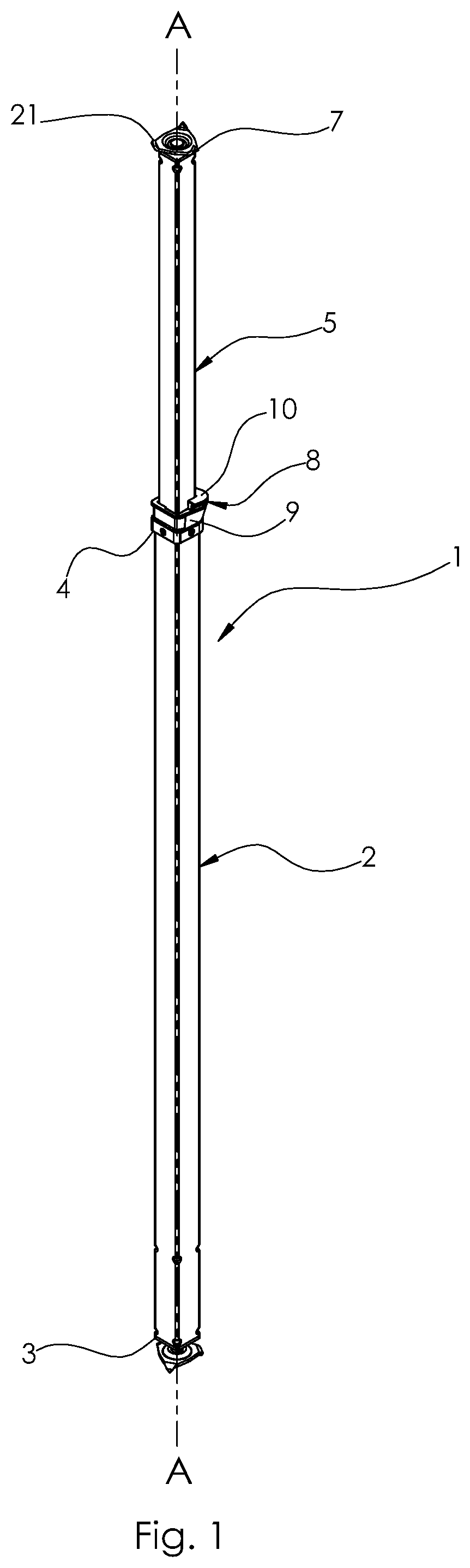
[0028]With reference, for example, to FIG. 1, there is provided an embodiment of a telescopic edge protection post 1. The telescopic edge protection post 1 is arrangeable between a floor and a ceiling. Typically, several telescopic edge protection posts 1 are arranged along an edge of a floor above the ground level, and fences are mounted on the telescopic edge protection posts 1 to prevent workers from falling over the edge. The telescopic edge protection post 1 comprises an outer tube 2 having a floor end 3 and a top end 4, an inner tube 5 having a bottom end 6, see FIG. 8, and a ceiling end 7. The inner tube 5 extends into the outer tube 2 and is movable with respect thereto between an extended position and a collapsed position. In other words, the outer and inner tubes 2, 5 are telescoping. In FIG. 1 an extended position of the telescopic edge protection post 1 is shown, though the telescopic edge protection post 1 has not been extended to a maximum length. Preferably, the outer...


PUM


Abstract

A telescopic edge protection post arrangeable between a floor and a ceiling, wherein the telescopic edge protection post comprises an outer tube having a floor end and a top end, and an inner tube having a bottom end and a ceiling end. The inner tube extends into the outer tube and is movable with respect thereto between an extended position and a collapsed position. The post further has a locking mechanism arranged to lock the inner tube with respect to the outer tube, and a tensioning device. The locking mechanism comprises a fixed element, which is attached to the outer tube at its top end, and a movable element, which is movable with respect to the fixed element between a locking position in which the movable element engages with the inner tube and the fixed element to prevent the inner tube from being retracted into the outer tube.

Description

FIELD OF INVENTION[0001]The present invention relates to a support post for an edge protection system. More particularly, it relates to a telescopic edge protection post comprising a tensioning device for mounting the edge protection post between two surfaces, typically a floor and a ceiling.TECHNICAL BACKGROUND[0002]Telescopic support posts can be used for edge protection systems in which they are temporarily arranged between support surfaces mounted at a construction or maintenance site to provide stable and safe working platforms. Mounted edge protection posts can furthermore provide attachment points for safety panels extending between two posts.[0003]U.S. Pat. No. 8,152,118 discloses a telescopic support post for a safety fence assembly comprising a tensioning and locking device comprising a collar element positioned at a top end of the outer tube and surrounding the inner tube. The tensioning and locking device further comprises a pivoting lever, which is arranged to move the ...

Claims


Application Information

Patent Timeline
IPC IPC(8): E04H12/18
CPCE04H12/182E04H17/21E04H17/22E04H17/009E04G21/3204E04G21/3233E04G2025/006E04G2025/042E04G25/08E04G25/066E04G25/04E04G25/065E04G2025/045F16B7/14
Inventor VIBERG, OLOVJÖNSSON, BENGT
Owner WXSAFE
Why Eureka
Try Eureka