Diffractive Projection Apparatus

Pending Publication Date: 2022-03-10
DIGILENS +1
View PDF7 Cites 6 Cited by
  • Summary
  • Abstract
  • Description
  • Claims
  • Application Information

AI Technical Summary

Benefits of technology

[0013]In one embodiment the laser illuminator comprises red, green and blue laser sources, a beam combiner and

Problems solved by technology

The above goals are not achieved by current technology.
Current wearable displays only manage to deliver see through, adequate pupils, eye relief and field of view and high brightness simultaneously at the expense of cumbersome form factors.
In many cases weight is distributed in the worst possible place for a wearable display, in front of the eye.
Microdisplays, which provide high-resolution image generators in tiny flat panels, do not necessarily help with miniaturizing wearable displays because the requirement for very high magnifications inevitably results in large diameter optics.
Several ultr

Method used


Image

  • Diffractive Projection Apparatus
  • Diffractive Projection Apparatus
  • Diffractive Projection Apparatus

Examples


Embodiment Construction

[0060]The invention will now be further described by way of example only with reference to the accompanying drawings.

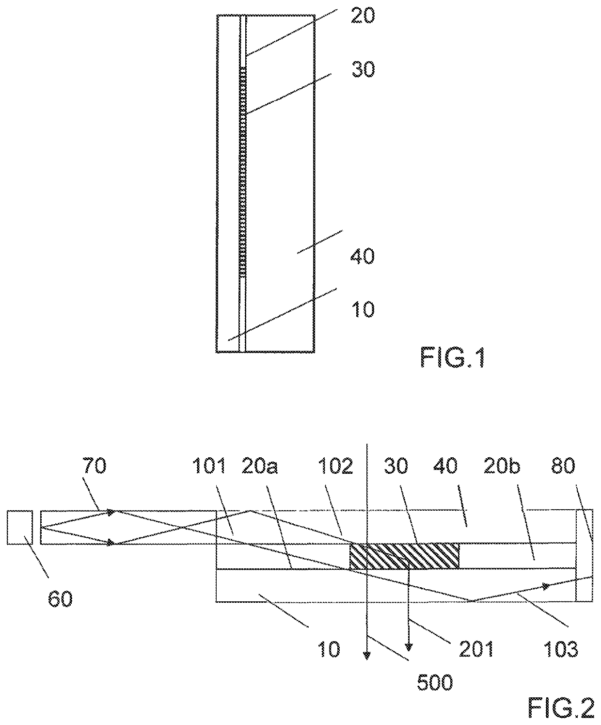
[0061]FIG. 1 shows a schematic side elevation view of a portion of one eyepiece of a wearable display in one embodiment of the invention. Although a planar element is shown the complete eyepiece may have a curved or facetted surface. The portion of the display shown in FIG. 1 comprises a DOE 10 an HPDLC layer comprising flood cured region indicated by 20 surrounding at least one independently switchable SBG region indicated by 30 and a transparent substrate layer 40. The HPDLC layer is sandwiched between the substrate and the DOE. Said SBG regions may be information symbols. Alternatively, the SBG regions may be configured to provide two dimensional pixelated arrays. In each case the SBGs are confined to the symbol or pixel regions the display being perfectly transparent elsewhere. The SBG and DOE together encode the characteristics of a lens whose function will be ex...


PUM

PropertyMeasurementUnit
Electric potential / voltageaaaaaaaaaa
Wavelengthaaaaaaaaaa
Brightnessaaaaaaaaaa

Abstract

A light projection apparatus is provided comprising: a source of light; a switchable grating on a first substrate; and a diffractive optical element. Light is diffracted at least once by the switchable grating and is diffracted at least once by the DOE.

Description

REFERENCE TO EARLIER FILINGS[0001]The present patent application is a continuation of a U.S. patent application having Ser. No. 13 / 998,799 filed on Dec. 11, 2011, which is a continuation of a U.S. patent application having Ser. No. 13 / 317,468 filed on Oct. 19, 2011 now U.S. Pat. No. 8,639,072 which issued on Jan. 28,2014, which is the national phase application of PCT application No.: PCT / GB2010 / 000835 filed 27 Apr. 2010, claiming priority to U.S. provisional patent application 61 / 202,996 filed on 27 Apr. 2010, all of which are incorporated herein by reference in their entireties.[0002]This application incorporates by reference in their entireties: PCT Application No.: US2008 / 001909, with International Filing Date: 22 Jul. 2008, entitled LASER ILLUMINATION DEVICE; U.S. patent application Ser. No. 10 / 555,661 filed 4 Nov. 2005 entitled SWITCHABLE VIEWFINDER DISPLAY; and PCT Application No. US2006 / 043938 with International Filing Date: 13 Nov. 2006, entitled METHOD AND APPARATUS FOR PR...

Claims


Application Information

Patent Timeline
IPC IPC(8): G02B27/01G02F1/29G02B26/10G02F1/1334G02B27/48G02B5/18G02B6/34
CPCG02B27/0172G02F1/292G02B26/105G02F1/13342G02B6/0011G02B27/48G02B5/1828G02B5/1876G02B6/34G02B26/101G03H2001/0439G03H2001/043G03H1/0408G02B5/32G03H2223/16G03H2223/23G03H2225/23G03H1/0248G03H2240/53G03H2260/33G03H2001/2226G03H2001/261G03H1/30G02B2027/0174G03H2270/55G03H2223/12G03H2223/18G03H2223/20G03H2223/24G03B13/02G02F2201/307G02B2027/0107G02B2027/0194G02B26/0808G03B21/10
Inventor WALDERN, JONATHAN DAVIDPOPOVICH, MILAN MOMCILO
Owner DIGILENS
Why Eureka
Try Eureka