
Hinged firearm receiver

a receiver and firearm technology, applied in the field of hinged firearm receivers, can solve the problems of reducing the accuracy of the receiver, reducing reducing so as to achieve the effect of reducing the accuracy of the receiver, and reducing the cost of the receiver

Active Publication Date: 2022-03-17
LAW TACTICAL LLC
View PDF1 Cites 0 Cited by
  • Summary
  • Abstract
  • Description
  • Claims
  • Application Information

AI Technical Summary

Benefits of technology

This configuration maintains the firearm's cycle rate and reliability while reducing length and weight, allowing for a more compact and efficient folding stock feature.

Problems solved by technology

Both lengthen the platform and add weight to the recoiling mass, altering firearm performance in terms of its rate of fire or reliability.

Method used


Image

  • Hinged firearm receiver
  • Hinged firearm receiver
  • Hinged firearm receiver

Examples


Embodiment Construction

[0045]And few of the preferred embodiments disclosed present illustration and description. Understandably, many modifications could be made without escaping the scope of the invention. Skilled artists will appreciate the many inventive concepts that qualify as equivalents under the claims. The embodiments described below do not limit the spirit of the invention nor the claims.

[0046]Every figure does not contain every reference number. Terms such as “forward,”“rearward,”“upper,”“lower,”“bottom,”“top,” and “side” are used to reference the orientations of the invention, as shown in the images. One skilled in the art will be able to distinguish how these orientational terms could change during the use of the invention.

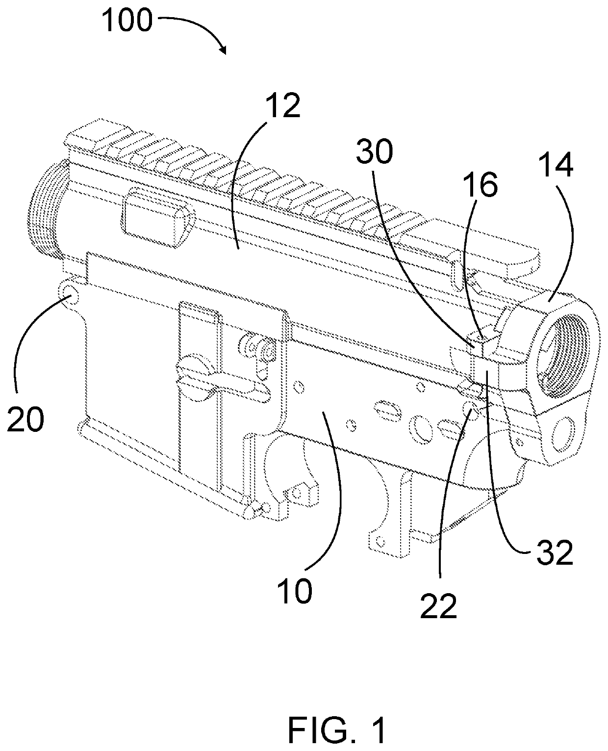
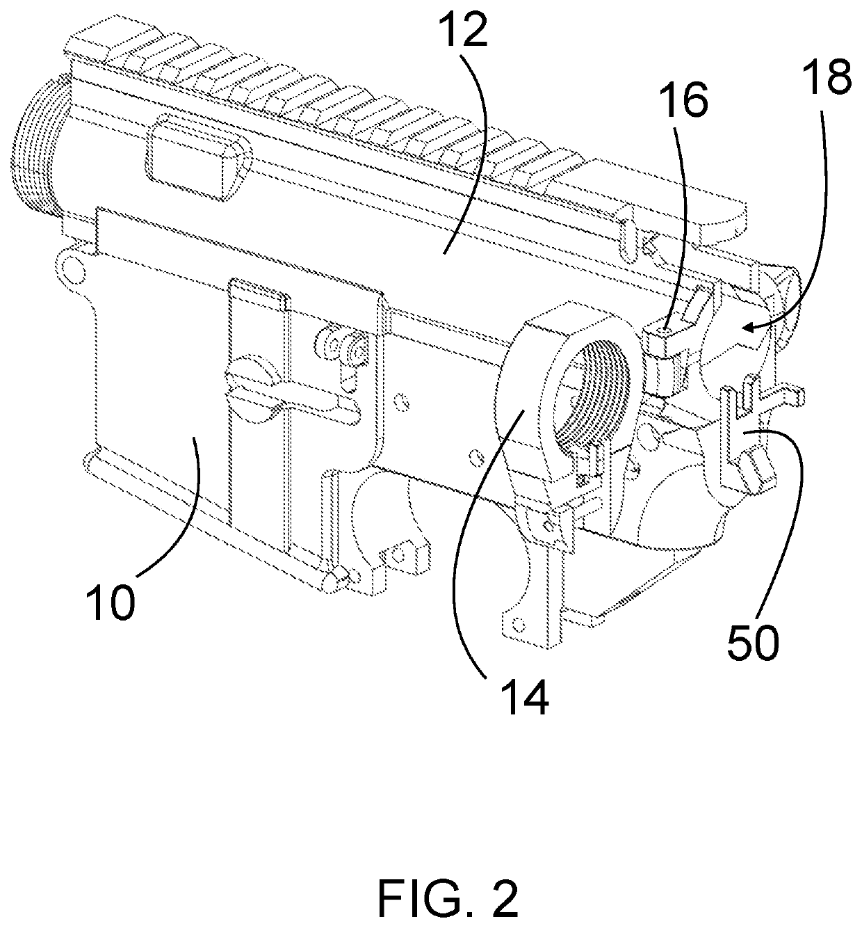
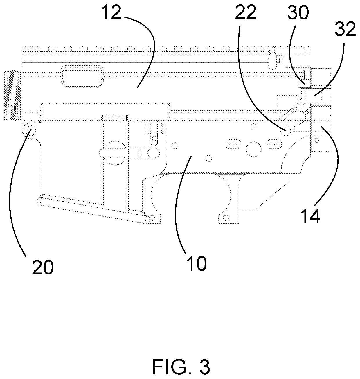
[0047]Three embodiments of the claimed invention are included in the drawings, not to limit inventions scope but to show how elements and features may be moved to different receiver sections to achieve the same goal of this invention. Embodiment Hinged Firearm Receiver 100...


PUM


Abstract

Provided is a hinged firearm receiver configured to operate with an AR-pattern Bolt carrier group, buffer, buffer spring, and buffer tube. The firearm upper receiver has an integral hinge that connects to a rear receiver body and provides an AR-pattern firearm the ability to have a folding stock to reduce length for storage or transportation purposes.

Description

CROSS-REFERENCE TO RELATED APPLICATION[0001]This application is a Continuation of U.S. patent application Ser. No. 17 / 019,289 filed on Sep. 13, 2020, entitled “Hinged Firearm Receiver,” which is hereby incorporated by reference in its entirety for all that is taught and disclosed therein.BACKGROUND[0002]The ability for a rifle to fold its stock is advantageous. It allows the rifle to reduce its size for transportation or storage significantly. AR-pattern rifles do not inherently have folding stocks due to the recoil buffer and spring being located within the stock portion of the firearm. This puts the AR-pattern firearm at a disadvantage in some scenarios when compared to rifles with a folding stock.[0003]Current inventions exist to provide the AR-pattern rifle with a folding stock capability. Adapters have been used to add a folding stock feature to standard AR-pattern receivers. For example, U.S. Pat. No. 8,769,855 B2. This adapter increases the length, weight, and complexity of t...

Claims


Application Information

Patent Timeline
Patent Type & Authority Applications(United States)
IPC IPC(8): F41A3/66F41A3/84
CPCF41A3/66F41A3/84F41A11/04F41C23/04
Inventor ROTH, PARKER MATTHEW
Owner LAW TACTICAL LLC
Learn More