Synthetic mechanically attached roof underlayment system

a mechanical attachment and underlayment technology, applied in the field of underlayment systems, can solve the problems of high cost of use of many underlayment structures and materials, including those of the type set forth above, and achieve the effect of reducing the “blanketing effect” and increasing the wind uplift performan

Active Publication Date: 2021-06-15
ARGUELLES DANIEL EFRAIN
View PDF123 Cites 3 Cited by
  • Summary
  • Abstract
  • Description
  • Claims
  • Application Information

AI Technical Summary

Benefits of technology

[0008]The present invention is directed to an economically beneficial, high-performance underlayment system structurally operative to increase wind uplift performance, through the use of a plurality of self-sealing mechanical fasteners. As practically applied, the mechanical fasteners serve to effectively secure a variety of different types of underlayment material in overlying relation to a roof deck or like support for the remainder of the roof structure. As a result, a “blanketing effect” is minimized in high wind zones. In addition, the underlayment system at least partially defines an enhanced platform for solar thermal tubing and thin-film photovoltaics, as used in foam adhered metal roofs and tile roof assemblies.

Problems solved by technology

Moreover, many of the underlayment structures and materials, including those of the type set forth above are expensive to use.

Method used


Image

  • Synthetic mechanically attached roof underlayment system
  • Synthetic mechanically attached roof underlayment system
  • Synthetic mechanically attached roof underlayment system

Examples


Embodiment Construction

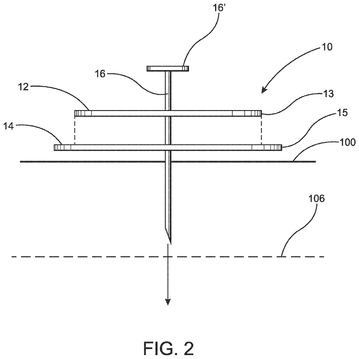
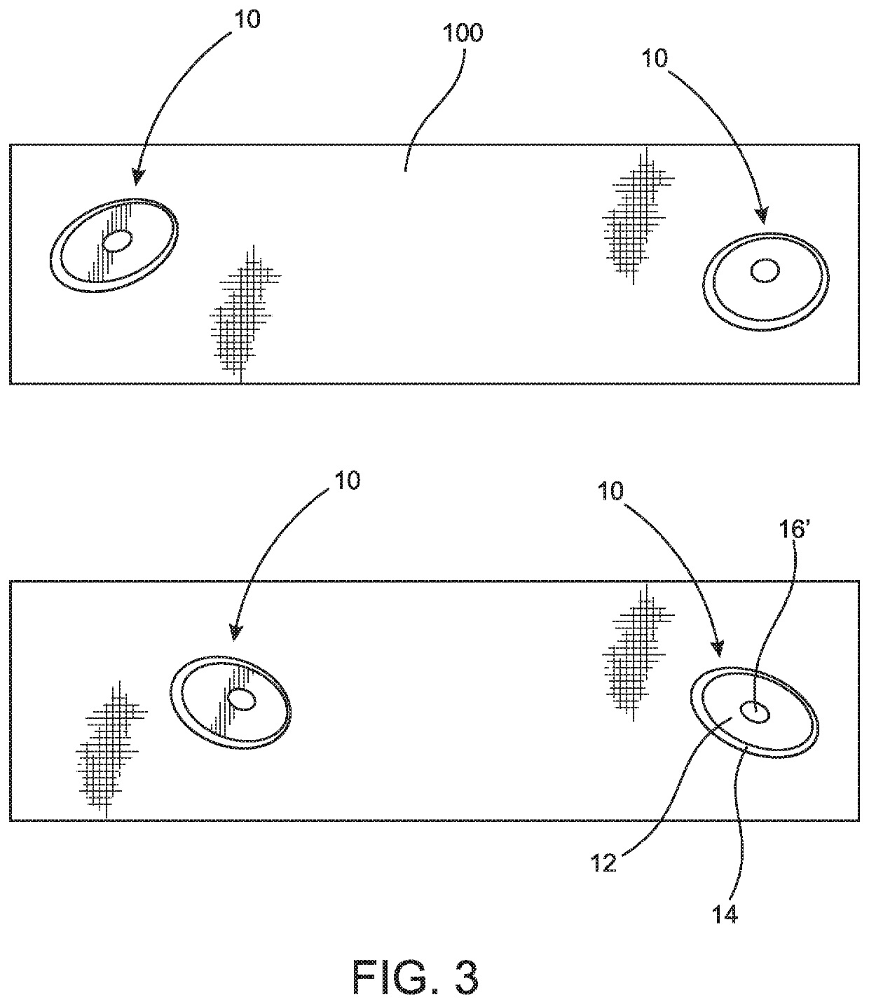
[0032]As represented in FIGS. 2-5 the present invention is directed to an underlayment system for a roof structure incorporating at least one but more practically a plurality of mechanical fasteners generally indicated as 10 or 10′ operatively positioned to retain a synthetic underlayment material 100 in covering relation to a roof deck or other underlying roof support structure 106.

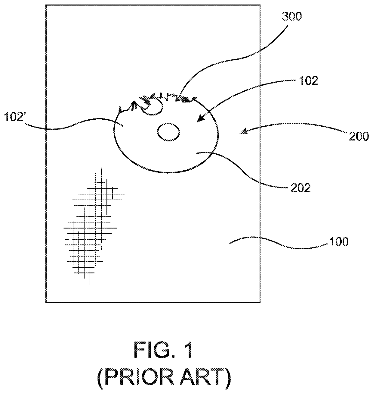
[0033]However, for purposes of clarity in further emphasizing the inventive structural and operative features of the present invention, reference is initially directed to FIG. 1, being representative of a conventional, known and / or prior art mechanical fastener generally indicated as 200, disposed in retaining engagement with underlayment material 100. More specifically, one or more different types of mechanical fasteners 200 typically include a retaining member 202 connected in overlying engagement with the outer surface of the underlayment material 100. Securement of the retaining member 202 in its int...


PUM


Abstract

An underlayment system for a roof structure including underlayment material disposed in covering relation to a roof deck and a plurality of mechanical fasteners disposed and structured to interconnect the underlayment material to the roof deck. Each mechanical fastener includes an outer plate, an under plate and a connector penetrating through both the outer plate and under plate in secured relation to the roof structure. The under plate is disposed and structured to sealing engage the connector penetrating there through. The under plate is further disposed in engagement with an undersurface of said outer plate and beneath and in segregating relation between an outer peripheral edge of the outer plate and the underlayment material.

Description

CLAIM OF PRIORITY[0001]The present application claims priority pursuant to 35 U.S.C. § 119(e) to U.S. Provisional Patent Application Ser. No. 62 / 800,166 filed on Feb. 1, 2019, the contents of which are incorporated herein, by reference, in their entirety.BACKGROUND OF THE INVENTIONField of the Invention[0002]The present invention is directed to an underlayment system for a roof structured to increase wind uplift performance through the utilization of a plurality of mechanical fasteners disposed in securing relation to an underlayment material overlying a roof deck or other support structure of the roof.Description of the Related Art[0003]In modern day construction, roof covering systems typically include an underlying, supporting deck or like support structure. This underlying support structure is covered by a water proof or leak resistant material that may take various forms. In addition, roof tiles, shingles and like roof coverings are frequently arranged and secured in overlappin...

Claims


Application Information

Patent Timeline
Patent Type & Authority Patents(United States)
IPC IPC(8): E04F13/21E04D5/14E04D12/00F16B15/02E04D1/34E04B1/38
CPCE04F13/21E04D5/145E04D12/002F16B15/02E04B2001/405E04D2001/3423E04B2001/389
Inventor ARGUELLES, DANIEL EFRAIN
Owner ARGUELLES DANIEL EFRAIN
Why Eureka
Try Eureka