Assembly of turbine engine parts comprising a fan blade having an integrated platform, and corresponding turbine engine

a technology of integrated platform and turbine engine, which is applied in the direction of machines/engines, liquid fuel engines, mechanical equipment, etc., can solve the problems of reducing performance, complex parts of blades, and reducing aerodynamics, so as to reduce movement, improve aerodynamics, and limit the impact of drag

Active Publication Date: 2021-07-06
SN DETUDE & DE CONSTR DE MOTEURS DAVIATION S N E C M A
View PDF13 Cites 0 Cited by
  • Summary
  • Abstract
  • Description
  • Claims
  • Application Information

AI Technical Summary

Benefits of technology

[0006]The object of the present invention is in particular to propose a solution that makes it possible to reduce the movements between the platforms of the fan blades made of a composite material, while improving the aerodynamic aspect and limiting the impact on drag.4. DISCLOSURE OF THE INVENTION
[0010]Thus, this solution allows the above-mentioned object to be achieved. In particular, the addition of a fin as an aerodynamic link system between the platforms both helps limit opposing transverse movements between the platforms which cause aerodynamic leakages, and helps guide and limit the passage vortices which are generated between the roots of the blades. Moreover, said fin makes it possible to reduce the vibrations to which the integrated platform blades are subjected in the region of the platforms, depending on the loadings. Said fin advantageously makes use of the rigidity at the mutual interface of the corresponding platforms.
[0011]According to an embodiment of the invention, the fin comprises a base extending radially on the inner side of the platforms, so as to lower overlap the longitudinal edges of the pressure face and suction face platform portions of adjacent blades. The base on the inner side, in addition to the existence of the fin radially on the outer side, benefits performance in terms of resistance to the centrifugal stresses to which the fan blades are subject. Moreover, the inner side and the outer side may result from non-interlinking of a 3D woven reinforcement preform of the composite blade, making for easier production for the impregnation of the preform with resin when casting the corresponding blade.
[0012]In an embodiment of the invention, the fin is attached between the adjacent pressure face and suction face platform portions. This configuration allows a mechanical link to be established between the adjacent platforms. Said attached fin also allows the aerodynamic properties of the fan to be improved, for example by promoting the mutual support of the platforms in optimised geometric conditions.
[0013]In another embodiment of the invention, the fin is made up of two fin portions which are each integral with one of the pressure face and suction face platform portions. This configuration allows the transverse movements between the platforms to be limited and also makes it possible to improve the aerodynamic properties of the root of the fan. When a base is present, said platforms improve the contact between the fins in order to reduce possible gaps there between under the effect of centrifugal stresses for example.
[0018]According to another feature of the invention, the longitudinal edges of the pressure face and suction face platforms are the result of a non inter-linking of the 3D weave. A feature of this kind allows the platforms of the blades to be strengthened. In particular, said non inter-linking occurs between the chain thread layers forming the platform portions intended to form a vane preform.

Problems solved by technology

The fan blade is a complex part, as its design requires a multi-disciplinary team which must cope at the same time with the aerodynamic, mechanical and acoustic aspects.
However, said blades may produce problems, for example manufacturing problems or problems of complying with requirements for assembly quality.
This could result in aerodynamic leakages and thus reduced performance.
Moreover, wear of the platforms at the junction thereof is a problem that must be considered.

Method used


Image

  • Assembly of turbine engine parts comprising a fan blade having an integrated platform, and corresponding turbine engine
  • Assembly of turbine engine parts comprising a fan blade having an integrated platform, and corresponding turbine engine
  • Assembly of turbine engine parts comprising a fan blade having an integrated platform, and corresponding turbine engine

Examples


Embodiment Construction

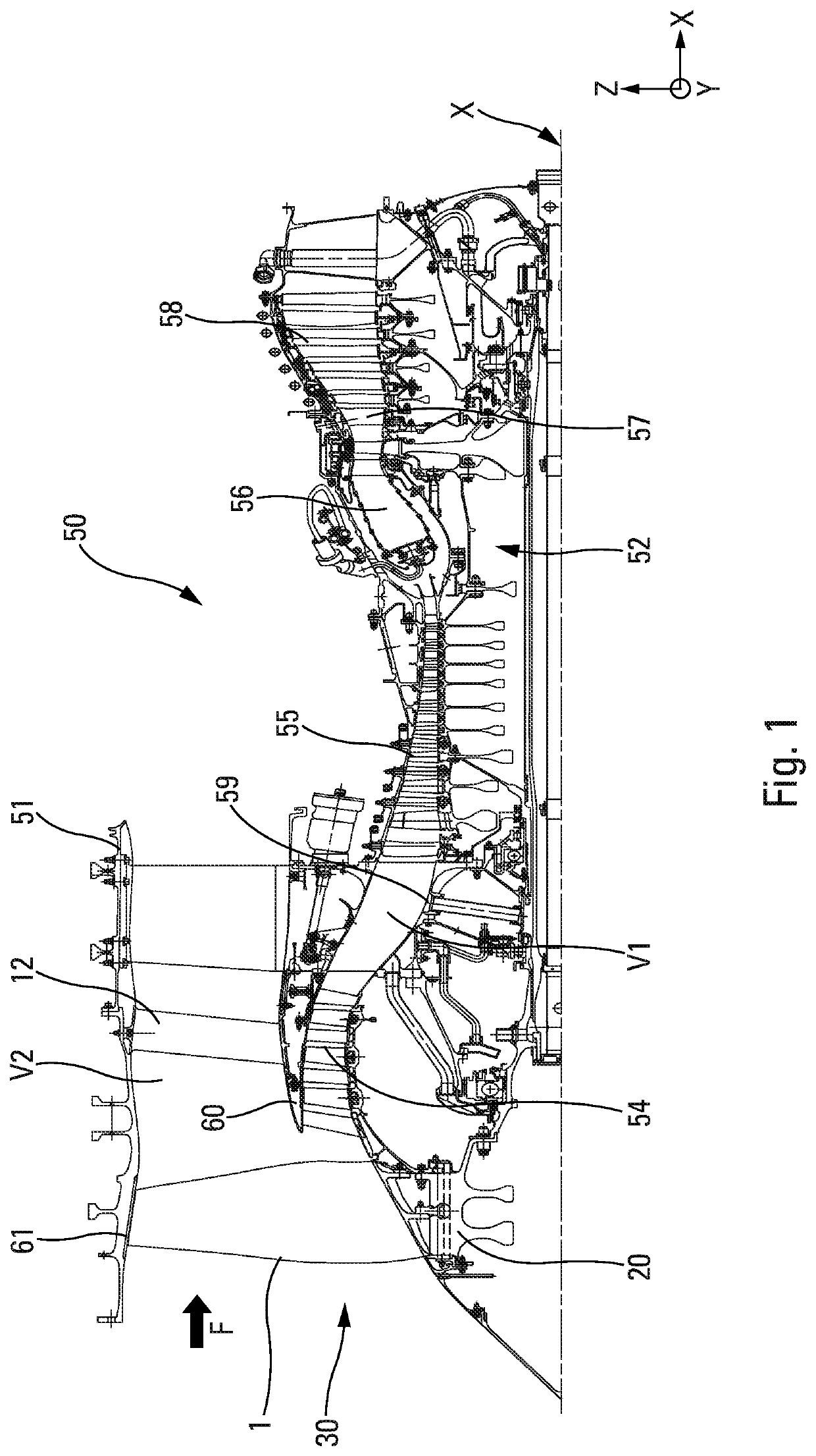
[0029]FIG. 1 shows a turbine engine 50 such as a turbojet engine for an aircraft, to which the invention relates. Said turbine engine 50 is in this case a dual-flow turbine engine which extends along a longitudinal axis X. The turbine engine 50 generally comprises an external nacelle 51 that surrounds a gas generator 52, upstream of which a fan 30 is mounted. In the present invention, and in a general manner, the terms ‘upstream’ and ‘downstream’ are defined in relation to the circulation of gases in the turbine engine. The terms ‘upper’, ‘lower’, ‘outer’ and ‘inner’ are defined in relation to a radial axis Z perpendicular to the axis X and in relation to the distance relative to the longitudinal axis X. A transverse axis Y is also perpendicular to the longitudinal axis X and to the radial axis Z. Said axes, X, Y, Z, shown in FIG. 1, form an orthonormal coordinate system.

[0030]In this example, the gas generator 52 comprises, from upstream to downstream, a low-pressure compressor 54,...


PUM


Abstract

The invention relates to an assembly of turbine engine (50) parts having a longitudinal axis (X), the assembly comprising at least two adjacent fan blades made of a 3D woven composite material, each blade (1) comprising a root (3), a vane (2) extending from the root (3), and an integrated platform (4) inserted between the root (3) and the vane (2), the platform (4) extending on either side of the vane (2) and forming a pressure face platform portion (4I) and a suction face platform portion (4E), the pressure face and suction face platform portions of adjacent blades being connected by a fin (14) extending at least radially at the outer side of the pressure face and suction face platform portions (4I, 4E), relative to the longitudinal axis (X), having a substantially triangular transverse cross section and extending axially and so as to upper overlap the longitudinal edges (11A, 11B) of the pressure face and suction face platform portions (4I, 4E) of the adjacent blades.

Description

1. FIELD OF THE INVENTION[0001]The present invention relates to the field of turbine engines and in particular to dual-flow turbine engines in which the airflows circulate from upstream downstream. It relates more specifically, but not exclusively, to an assembly of turbine engine parts comprising fan blades having an integrated platform.2. PRIOR ART[0002]Dual-flow turbine engines comprise, in a known manner, a movable fan arranged upstream of a gas generator according to the circulation of gases in the turbine engine. The gas generator is housed in an annular inner casing while the fan is housed in an annular outer casing. Said inner and outer casings are separated by an annular inter-duct casing so as to delimit a primary duct and a secondary duct. The fan comprises a plurality of fan blades and a disc, from which each blade extends substantially radially. The free ends of the blades face the outer casing so as to compress an incident air flow at least in the secondary duct and, p...

Claims


Application Information

Patent Timeline
Patent Type & Authority Patents(United States)
IPC IPC(8): F01D11/00F01D5/22F01D5/28F04D29/32F04D29/64F04D29/08F04D29/66F01D5/14
CPCF01D11/008F01D5/143F01D5/22F01D5/282F01D11/006F04D29/083F04D29/322F04D29/324F04D29/644F04D29/667F01D5/146F01D5/147F05D2220/36F05D2240/80F05D2250/11F05D2250/23F05D2260/30F05D2300/603Y02T50/60
Inventor DUBOSC, MATTHIEU PIERRE MICHELBULOT, BENJAMIN
Owner SN DETUDE & DE CONSTR DE MOTEURS DAVIATION S N E C M A
Why Eureka
Try Eureka