
Patsnap Eureka
For R&D, Patsnap Eureka makes reading and utilizing patents & technical documents easy.
Patsnap Eureka AIR
Designed for self-driven R&D workflows. Generate viable solutions, solve complex R&D challenges, empower your innovation with AI.

Patsnap Eureka Materials
Designed for material experts only. Revolutionize your material R&D, from search, analyze, to developing new materials.

TechResearch
Generate reliable direction feasibility study reports for your R&D in just a few steps.

TechSeek
Discover and master advanced knowledge NOW. Basics, ideas, possibilities, all at once.

TechMind
As an expert in R&D Theories, TechMind can generates customized viable solutions instantly.

TechRisk
Analyze your overall solution with one click, know your potential R&D risks in advance.

TechMonitor
Get weekly tech updates, stay abreast of the latest tech innovations and key insights.
Electric power supply system
a technology of power supply system and power supply circuit, which is applied in the direction of secondary cell servicing/maintenance, safety/protection circuit, batteries, etc., can solve the problem of complicated connection of the switch
- Summary
- Abstract
- Description
- Claims
- Application Information
AI Technical Summary
Benefits of technology
Problems solved by technology
Method used
Image

Examples
first embodiment
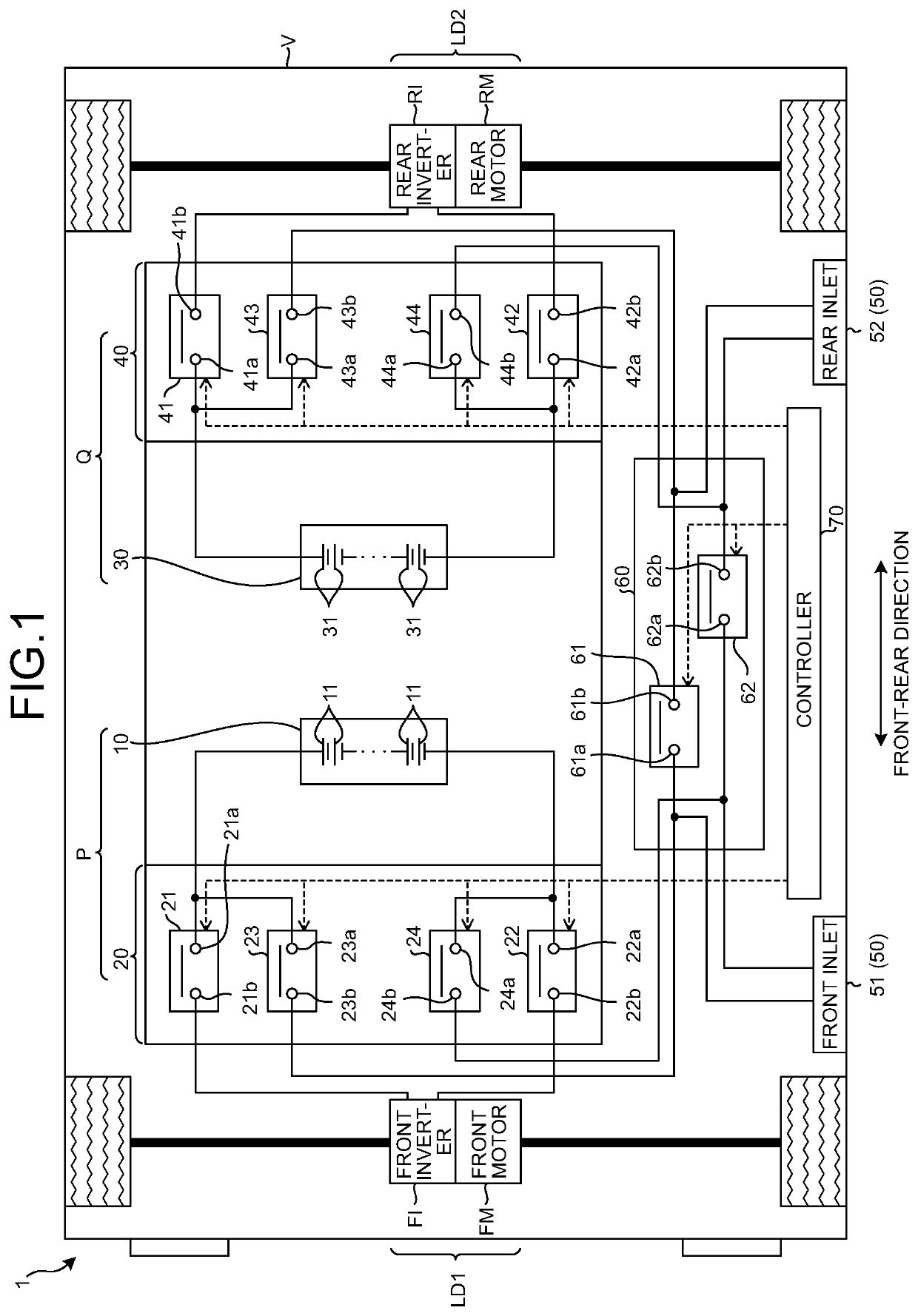
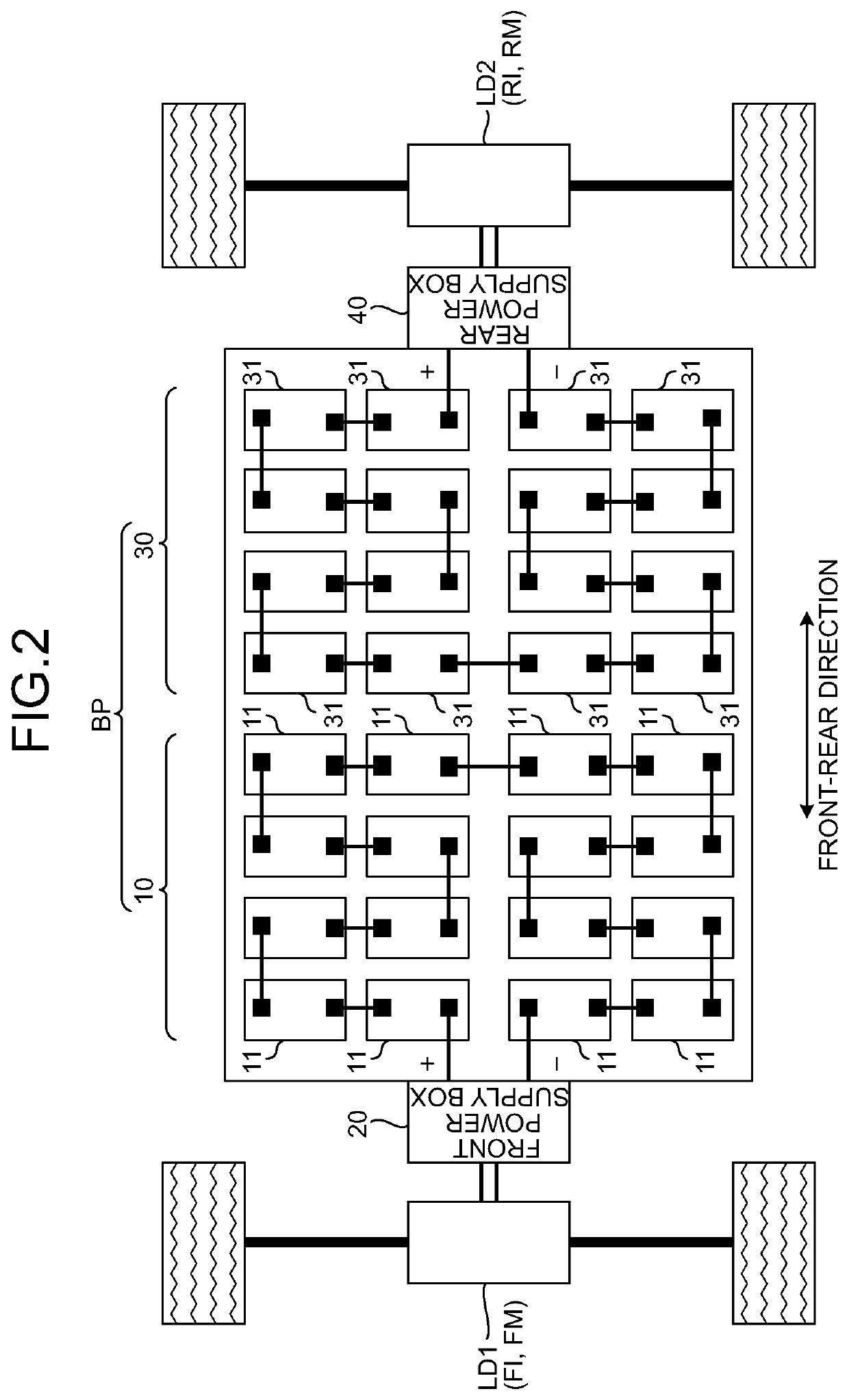
[0029]An electric power supply system 1 according to an embodiment will be described with reference to the drawings. FIG. 1 is a block diagram illustrating a configuration example of the electric power supply system 1 according to a first embodiment. FIG. 2 is a block diagram illustrating a configuration example of a battery pack BP according to the first embodiment.
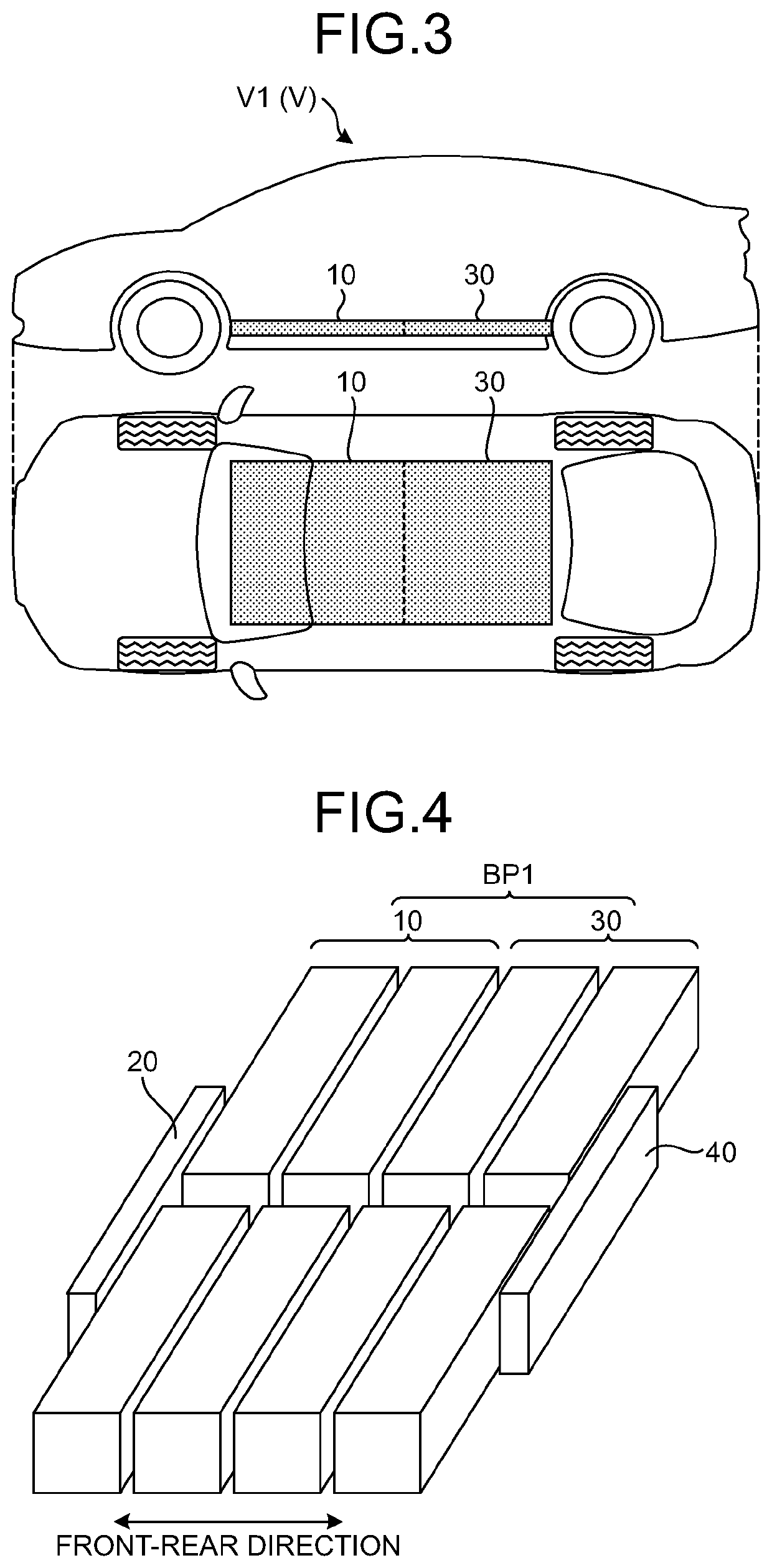
[0030]The electric power supply system 1 according to the embodiment is mounted on, for example, an electric motor vehicle (vehicle) V such as electric vehicles (EVs), charges electric power supplied by an external charging device, and supplies the charged electric power to a load unit.
[0031]Here, in the following description, the direction along the front and rear of the vehicle V is referred to as a front-rear direction. It can be said that the front-rear direction is referred to as a straight direction that is the direction along which the vehicle V travels straight or a whole length direction that is the direction ov...
second embodiment
[0075]Next, an electric power supply system 1A according to a second embodiment will be described. In the description of the second embodiment, the same components as those of the electric power supply system 1 according to the first embodiment are designated by the same reference numerals, and detailed description thereof will not be repeated. FIG. 14 is a block diagram illustrating a configuration example of the electric power supply system 1A according to the second embodiment. The electric power supply system 1A according to the second embodiment can perform a battery equalization process, and is different from the electric power supply system 1 according to the first embodiment in that electric power can be supplied from a normal battery to a first load unit LD1 and a second load unit LD2 in a case where one of the batteries is abnormal.
[0076]As illustrated in FIG. 14, the electric power supply system 1A according to the second embodiment includes a first supply system P, a sec...
modified example
[0096]In the above description, the example in which the first supply system P is provided on the front side of the vehicle V in the front-rear direction and the second supply system Q is provided on the rear side with respect to the first supply system P has been described, but the dispositions of the first supply system P and the second supply system Q are not limited thereto, and may be disposed in other ways.
[0097]The example in which the front inlet 51 is provided on the front side of the vehicle V in the front-rear direction and the rear inlet 52 is provided on the rear side with respect to the front inlet 51 has been described, but the dispositions of the front inlet 51 and the rear inlet 52 are not limited thereto, and may be disposed in other ways.
[0098]The example in which the electric power supply system 1 is mounted on, for example, the electric vehicles (EVs) has been described, but the electric power supply system 1 is not limited thereto, and for example, the electric...
PUM
 Abstract
Description
Claims
Application Information
 - R&D Engineer
- R&D Manager
- IP Professional
- Industry Leading Data Capabilities
- Powerful AI technology
- Patent DNA Extraction
Browse by: Latest US Patents, China's latest patents, Technical Efficacy Thesaurus, Application Domain, Technology Topic, Popular Technical Reports.
© 2024 PatSnap. All rights reserved.Legal|Privacy policy|Modern Slavery Act Transparency Statement|Sitemap|About US| Contact US: help@patsnap.com