Striated fiber-based concrete reinforcement

a fiber-based concrete and striated technology, applied in the direction of building components, structural elements, constructions, etc., can solve the problem of uneven steel rods

Pending Publication Date: 2022-03-31
RGT UNIV OF MICHIGAN
View PDF2 Cites 0 Cited by
  • Summary
  • Abstract
  • Description
  • Claims
  • Application Information

AI Technical Summary

Benefits of technology

[0008]In accordance with another aspect of the disclosure, a fiber for reinforcing concrete including a steel rod having a surface, and a series of striations in the surface of the steel rod. The series of striations are arranged in a striation pattern.
[0009]In accordance with yet another aspect of the disclosure, a method of manufacturing a fiber to be embedded in concrete for reinforcement of the concrete includes providing the fiber to a press, the press comprising a pair of press pieces, the pair of press pieces being spaced apart from one another by a gap, the pair of press pieces comprising at least one rounded press piece, rotating the rounded press piece, feeding the fiber through the gap between the pair of press pieces, the gap being smaller than a diameter of the fiber, and cutting the fiber into fiber sections after feeding the fiber through the gap. At least one of the pair of press pieces includes a set of teeth configured to striate the fiber to form a series of striations in the fiber having a striation pattern in accordance with the set of teeth.
[0010]In connection with any one of the aforementioned aspects, the structures and/or methods described herein may alternatively or additionally include any combination of one or more of the following aspects or features. The concrete matrix includes a plurality of shear keys, each shear key of the plurality of shear keys including a respective portion of the concrete matrix disposed in a respective striation of the series of striations. The fiber has a longitudinal axis. The series of striations do not modify the longitudinal axis of the fiber. The longitudinal axis is a straight axis for an entire length of the fiber. At least a subset of the series of striations is elongated in a direction transverse to the longitudinal axis. At least a subset of the series of striations is elongated in a direction oriented on a diagonal relative to the longitud...

Problems solved by technology

The surface of the steel rod has abrasions outside of the series of stria...

Method used


Image

  • Striated fiber-based concrete reinforcement
  • Striated fiber-based concrete reinforcement
  • Striated fiber-based concrete reinforcement

Examples


Embodiment Construction

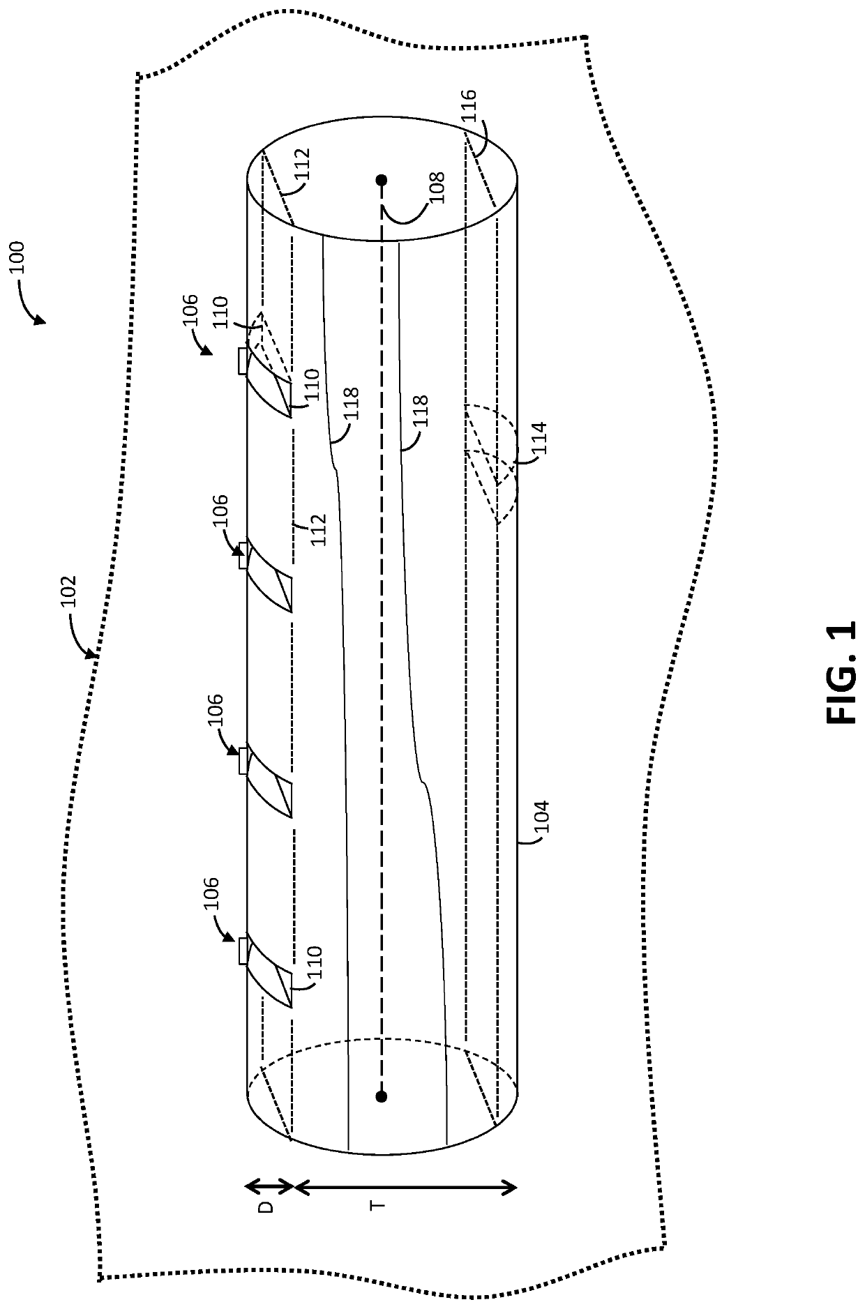
[0021]Concrete reinforcement fibers with striation patterns, and composite structures having such striated fibers, are described. Systems and methods of manufacturing the striated fibers are also described. Striation of the surface of the fiber improves the bond between the fiber and the concrete matrix. The striations may exploit and / or interfere with a surface characteristic of the fibers that establishes a bond between the fiber and the concrete matrix. Higher tensile strength levels are thus achieved for a given amount / number of fibers. Alternatively or additionally, the improved bond may allow fewer fibers to be used to achieve a desired level of pullout strength and / or bond resistance, thereby reducing the overall cost of the concrete.

[0022]The disclosed fibers may be embedded in a matrix of ultrahigh performance concrete. The matrix of the ultrahigh performance concrete seeps into, or otherwise becomes disposed in, the striations. The concrete matrix resists fiber pullout thr...


PUM

PropertyMeasurementUnit
Lengthaaaaaaaaaa
Diameteraaaaaaaaaa

Abstract

A composite structure includes a concrete matrix and a fiber embedded in the concrete matrix. The fiber includes steel. A surface of the fiber has a series of striations. The series of striations are arranged in a striation pattern.

Description

CROSS-REFERENCE TO RELATED APPLICATION[0001]This application claims the benefit of U.S. provisional application entitled “Striated Fiber-Based Concrete Reinforcement,” filed Jan. 10, 2019, and assigned Ser. No. 62 / 790,776, the entire disclosure of which is hereby expressly incorporated by reference.BACKGROUND OF THE DISCLOSUREField of the Disclosure[0002]The disclosure relates generally to fiber-based concrete reinforcement.Brief Description of Related Technology[0003]Cement structures are brittle in nature. A cement matrix has a compressive strength much higher than its tensile strength. Cement structures thus tend to crack under tensile stresses.[0004]Various fibers have been added to a cement matrix to improve the tensile and bending strength, energy absorption, and toughness of the resultant cement structure. For instance, glass and carbon fibers have been used in bundles or strands, each strand having a number of filaments. Polymeric fibers have various forms, including monofil...

Claims


Application Information

Patent Timeline
IPC IPC(8): C04B14/48E04C5/03
CPCC04B14/48E04C5/03C04B28/02C04B32/02
Inventor EL-TAWIL, SHERIFTAI, YUH-SHIOU
Owner RGT UNIV OF MICHIGAN
Why Eureka
Try Eureka