Removable support interface for an annular turbomachine casing

a support arm and annular turbomachine technology, applied in the direction of machines/engines, mechanical equipment, transportation and packaging, etc., can solve the problems of increased engine weight, risk of poor suspension behaviour of the support arm, and significant wear of the threads of the bolts and pins, so as to achieve easy and quick fixation and safe suspension

Active Publication Date: 2022-03-31
SN DETUDE & DE CONSTR DE MOTEURS DAVIATION S N E C M A
View PDF4 Cites 0 Cited by
  • Summary
  • Abstract
  • Description
  • Claims
  • Application Information

AI Technical Summary

Benefits of technology

[0035]As previously mentioned, it is easy and quick to fix support interfaces according to the invention on an annular casing to ensure a safe suspension for any type of intervention on the turbomachine.

Problems solved by technology

These thickenings increases the weight of the engine.
However, the interventions requiring the handling of turbomachines can be numerous during the life of a turbomachine, so that these support interfaces have to be assembled and disassembled a large number of times, which can lead to significant wear of the threads of the bolts and tapping of the pins and therefore a risk of poor suspension behaviour of the engine by the support arms.
In this way, even if these removable support interfaces meet the weight constraint induced by the permanent support of the bosses on the annular casing, the means for fixing these support interfaces to the annular casing do not allow the turbomachine to be held securely in suspension over the long term.

Method used


Image

  • Removable support interface for an annular turbomachine casing
  • Removable support interface for an annular turbomachine casing
  • Removable support interface for an annular turbomachine casing

Examples


Embodiment Construction

[0049]In this presentation, the terms “internal” and “external” are used to refer to a positioning relative to the axis of rotation of an axial turbomachine.

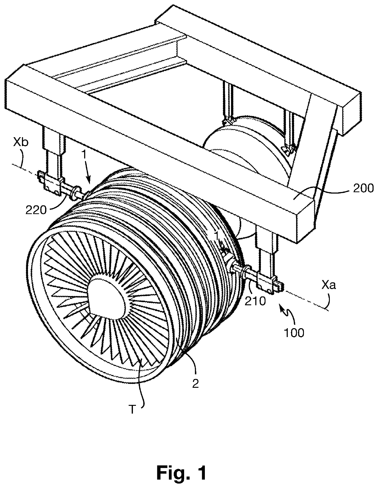
[0050]The FIG. 1 shows a support device 100 in cooperation with an annular casing 2 of a fan of a turbomachine T, such as, for example, an intermediate annular casing. The support device 100 comprises a frame 200, two support arms 210, 220 connected to the frame 200 and extending along respective horizontal longitudinal axis Xa, Xb. In the position mounted on the support device 100, and as described in more detail below, the annular casing 2 is therefore supported by the support arms 210, 220 via the two support interfaces 1.

[0051]Displacement means (not shown) allow each support arm 210, 220 to be moved, in particular along its longitudinal axis Xa, Xb.

[0052]As shown in the FIG. 1, the support arms 210, 220 are positioned substantially opposite each other and in such a way that there is sufficient space between them to accommod...


PUM


Abstract

The disclosure provides a removable support interface for an annular turbomachine casing, the removable interface having a coupling part configured for being mounted on the casing, and at least one attachment element for suspending the casing, orifices arranged in the coupling part the interface having means for locking the coupling part to the casing.

Description

TECHNICAL FIELD[0001]The present invention concerns a support interface. More particularly, the invention concerns a support interface for an engine casing, in particular of an aeronautical engine such as a turbomachine, which is adapted to be used during the manufacture or the handling of the engine.[0002]The invention also relates to an annular turbomachine casing configured to receive such a support interface. It also concerns an assembly comprising such an annular casing and such a support interface, as well as a turbomachine comprising such an assembly. Finally, the present invention concerns a method of handling such a casing by means of such a support interface.PRIOR ART[0003]The prior art includes documents FR-A1-3 041 376, WO-A1-2015 / 114276, WO-A1-2017 / 203139, FR-A1-3 051 833 and FR-A1-3 018 773.[0004]When handling the turbomachines, for example during assembly or maintenance procedures, it is often necessary to support them in an elevated position to allow an easier access...

Claims


Application Information

Patent Timeline
Patent Type & Authority Applications(United States)
IPC IPC(8): F01D25/28
CPCF01D25/285F05D2230/60B64F5/50F01D25/24F05D2260/02Y02T50/60
Inventor MEYER, JULIEN ALAINHAENTJENS, BRUNO MARIE-JOSEPH ANNE PADOUEQUERNET, LUC BERNARD JEANPERSE, ERWAN PIERRE ANTOINETHOMAZO, MAXIME JULIEN
Owner SN DETUDE & DE CONSTR DE MOTEURS DAVIATION S N E C M A
Why Eureka
Try Eureka