Air conditioning system, control unit and other components used therewith

a technology of air conditioning system and control unit, which is applied in the direction of domestic cooling apparatus, heating types, instruments, etc., can solve the problem of difficult rewiring job and other problems, and achieve the effect of improving the efficiency of the system

Active Publication Date: 2011-11-08
RANKICH STEPHEN
View PDF1 Cites 1 Cited by
  • Summary
  • Abstract
  • Description
  • Claims
  • Application Information

AI Technical Summary

Benefits of technology

[0005]Our air conditioning system for a building removes the need to run wires from the master controller to the air-cooling unit, facilitating quick and simple repair of severed wires and simplifying installing new air conditioning systems. Our air conditioning system includes the conventional components: An evaporator within the building and a compressor at a remote location exterior to the building that is under the control of a switching device. The compressor may be single stage or two-stage. In the case of a two-stage compressor, a pair of switching devices may be employed. The compressor is connected to the evaporator by a line that extends into the building and through which a refrigerant is cycled between the compressor and the evaporator. A directional flow control valve in the line to the compressor may be used so the system functions as a heat pump. A thermostat within the building responds to temperature changes to provide a temperature control or command signal.
[0008]Two, the receiver and transmitter devices may include multiple terminals. The transmitter device terminals correspond to the number of terminals of the receiver device. The multiple terminals employed enable connection to a transformer and the switching device for the single compressor or a pair of switching devices for the two-stage compressor or a switching device for the electronically actuated directional flow control valve. The transmitter and receiver devices are compact circuit boards that are easy and quick to install and connect to the conventional elements of our air conditioning system.

Problems solved by technology

Consequently, if this wire X is severed, a difficult rewiring job may be required to reestablish a connection between the relay 4 and the master controller 20.

Method used


Image

  • Air conditioning system, control unit and other components used therewith
  • Air conditioning system, control unit and other components used therewith
  • Air conditioning system, control unit and other components used therewith

Examples


Embodiment Construction

.” The claims that follow define our air conditioning system, control unit and other components used therewith, distinguishing them from the prior art; however, without limiting the scope of our air conditioning system, control unit and other components used therewith as expressed by these claims, in general terms, one or more, but not necessarily all, of their features are:

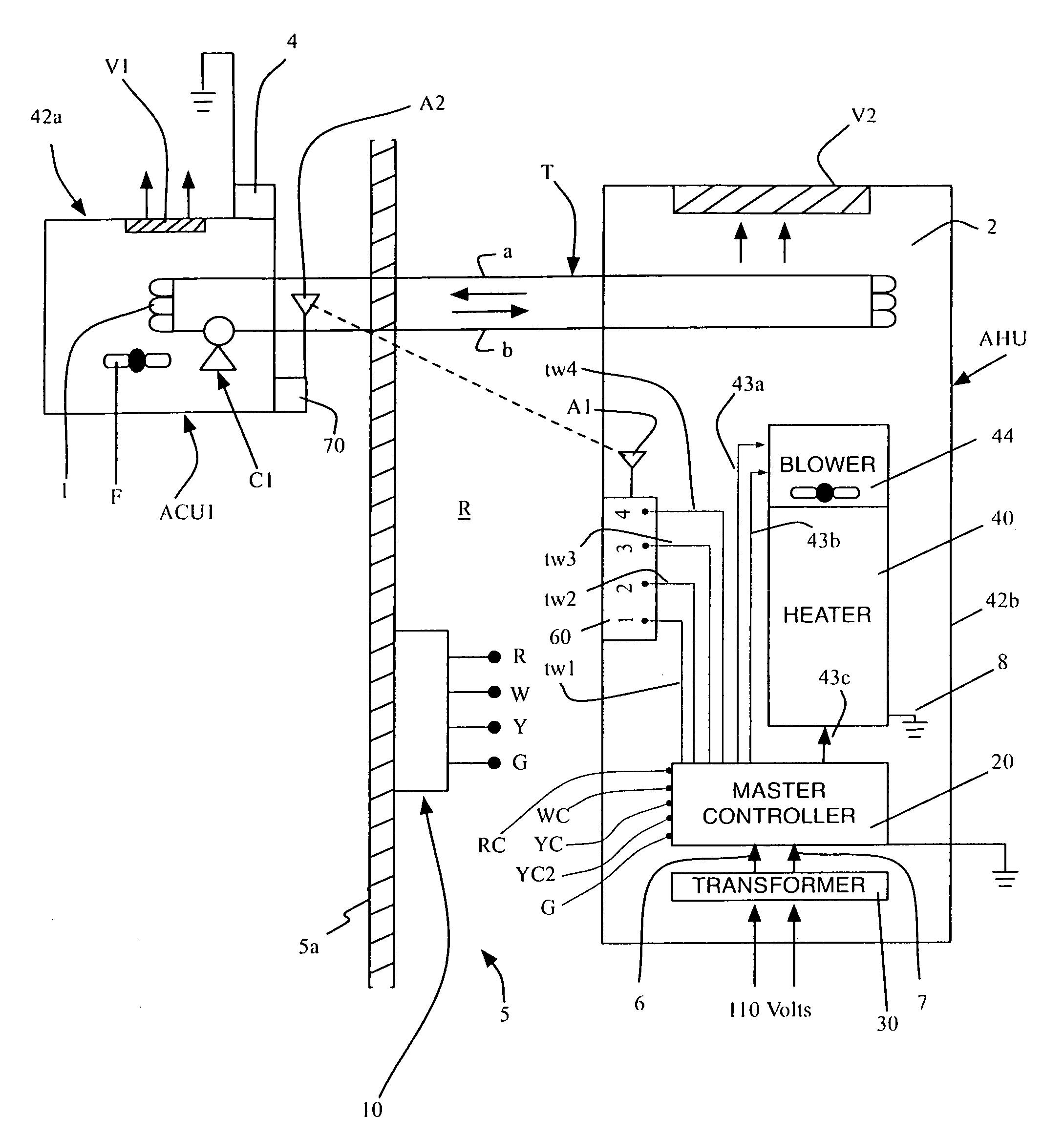
[0007]One, our system uses unique control units. In one embodiment, two different control units are used. A first control unit has an especially designed transmitter device and a second control unit uses an especially designed receiver device at or nearby the compressor. The first control unit includes a transmitter within the building that is electrically connected to the thermostat and in response to the temperature control signal transmits a radio frequency (RF) control signal to a receiver in the second control unit. The receiver responds to the RF control signal to control the operation of the compressor, in...


PUM


Abstract

An air-conditioning system operable at different states employs a control unit including a receiver and a transmitter. The receiver is connected electrically to a switching device for a compressor of the air-conditioning system. The compressor is installed at a remote location exterior to a building. The receiver is responsive to an encoded radio signal to provide an electronic control signal for actuating the switching device. The transmitter is installed within the building and is electrically connected to a thermostat within the building that responds to temperature changes to provide a temperature control signal. The transmitter upon receipt of the temperature control signal transmits to the remote location the encoded radio signal for operating the air-conditioning system at one of the different states.

Description

RELATED PATENT APPLICATIONS & INCORPORATION BY REFERENCE[0001]This utility application claims the benefit under 35 USC 119(e) of U.S. Provisional Patent Application No. 60 / 948,592, entitled “AIR CONDITIONING SYSTEM, CONTROL UNIT & OTHER COMPONENTS USED THEREWITH,” filed Jul. 9, 2007. This related application is incorporated herein by reference and made a part of this application. If any conflict arises between the disclosure of our invention in this utility application and that in the related provisional application, the disclosure in this utility application shall govern. Moreover, any and all U.S. patents, U.S. patent applications, and other documents, hard copy or electronic, cited or referred to in this application are incorporated herein by reference and made a part of this application.DEFINITIONS[0002]The words “comprising,”“having,”“containing,” and “including,” and other forms thereof, are intended to be equivalent in meaning and be open ended in that an item or items follow...

Claims


Application Information

Patent Timeline
Patent Type & Authority Patents(United States)
IPC IPC(8): G05D23/00G08B1/08G01M1/38
CPCF24F11/0012G05D23/1905F24F2011/0067F24F2011/0068F24F11/30F24F2110/10F24F11/54F24F11/56F24F11/84F24F11/88F24F11/63F24F11/86
Inventor RANKICH, STEPHENIEST, JOHN
Owner RANKICH STEPHEN
Why Eureka
Try Eureka