Connector for cables

a technology of connecting cables and cables, applied in the direction of coupling device connections, applications, surgery, etc., can solve the problems of difficult to carry out, a1 is particularly complex, and the connector according is difficult to achieve, and achieves the effect of substantial rapidity and simplicity

Pending Publication Date: 2022-03-31
UNIV GRENOBLE ALPES +2
View PDF0 Cites 2 Cited by
  • Summary
  • Abstract
  • Description
  • Claims
  • Application Information

AI Technical Summary

Benefits of technology

[0032]Each one among the first and second blocks are configured to be connected together by a relative connection movement of one with respect to the other, preferably by a relative movement of the connection face of one with respect to the connection face of the other, the pistons fastened to the first ends of the first cables and the pistons fastened to the first ends of the second cables being configured to be connected, in pairs, according to said relative movement, when the first and second locking components are in the locking position. The connector thus makes it possible, in the same movement, to connect both the first and second blocks together and each pair of cables together by their pistons when the first and second locking components are in the locking position. This makes it possible to guarantee substantial simplicity and substantial rapidity of use of the connector, and consequently of the cabled robot.
[0033]According to another characteristic, the first locking component is configured pour alternatively lock and release all the pistons fastened to the first ends of the first cables and wherein the second locking component is configured to alternatively lock and release all the pistons fastened to the first ends of the second cables. The connector thus allows for a robust locking of the first ends of the first and second cables by engaging...

Problems solved by technology

When the surgical tool is a complete robot, this is difficult to carry out because the robot has to be able to completely enter, including its motors, its control box, etc., the sterilisation tool.
Furthermore, when certain components of the robot are not compatible with the sterilisation method, a way must be found to disconnect the portion of the robot, which can be sterilised or is to be sterilised, because having been or being intended for being put into contact with the patient, of the portion that is incompatible with the sterilisation.
The connector according to patent document US 2006/0052664 A1 is parti...

Method used


Image

  • Connector for cables
  • Connector for cables
  • Connector for cables

Examples


Embodiment Construction

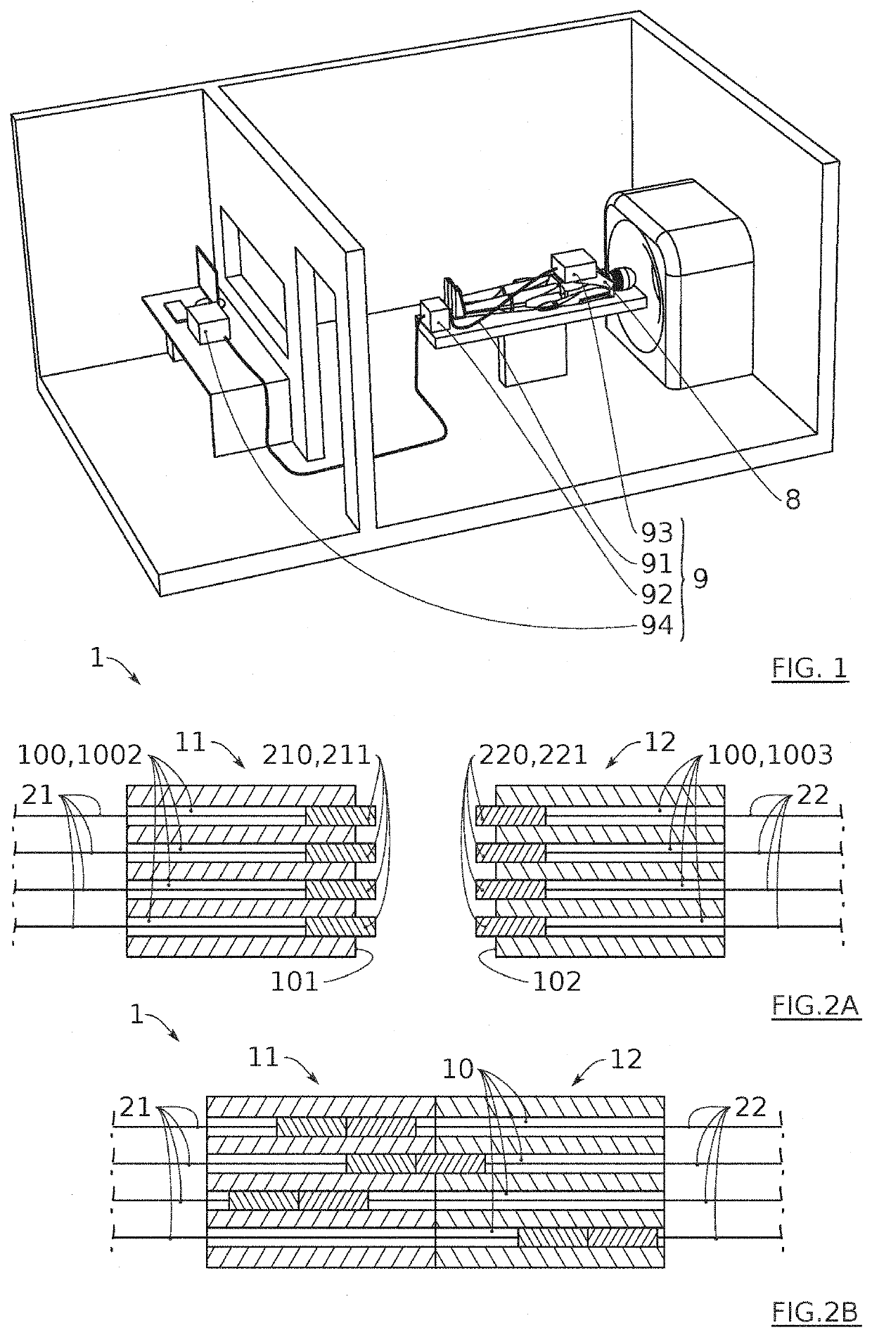
[0068]The present invention relates, according to its first aspect, to a connector for cables, and in particular for flexible cables, intended for making it possible to very quickly and easily connect a large quality of cables together. The connector according to the invention aims more particularly to connect together, on the one hand an instrument or an instrument element, on the other hand a motorised rotor assembly, of a cabled robot. Thus, according to the second aspect, the invention relates to a cabled robot comprising a connector according to the first aspect of the invention. Storage / displacement and / or cleaning / sterilisation of the cabled robot is greatly facilitated due to the fact that it comprises the connector according to the first aspect of the invention.

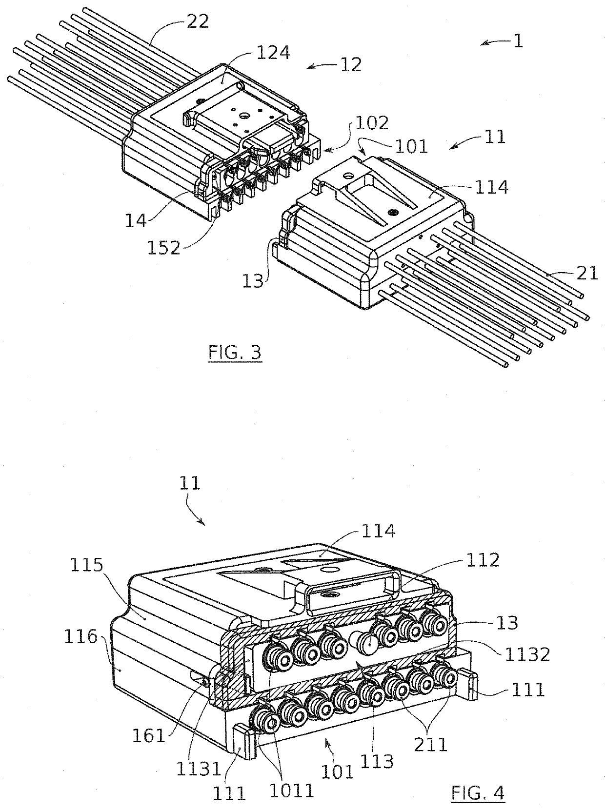
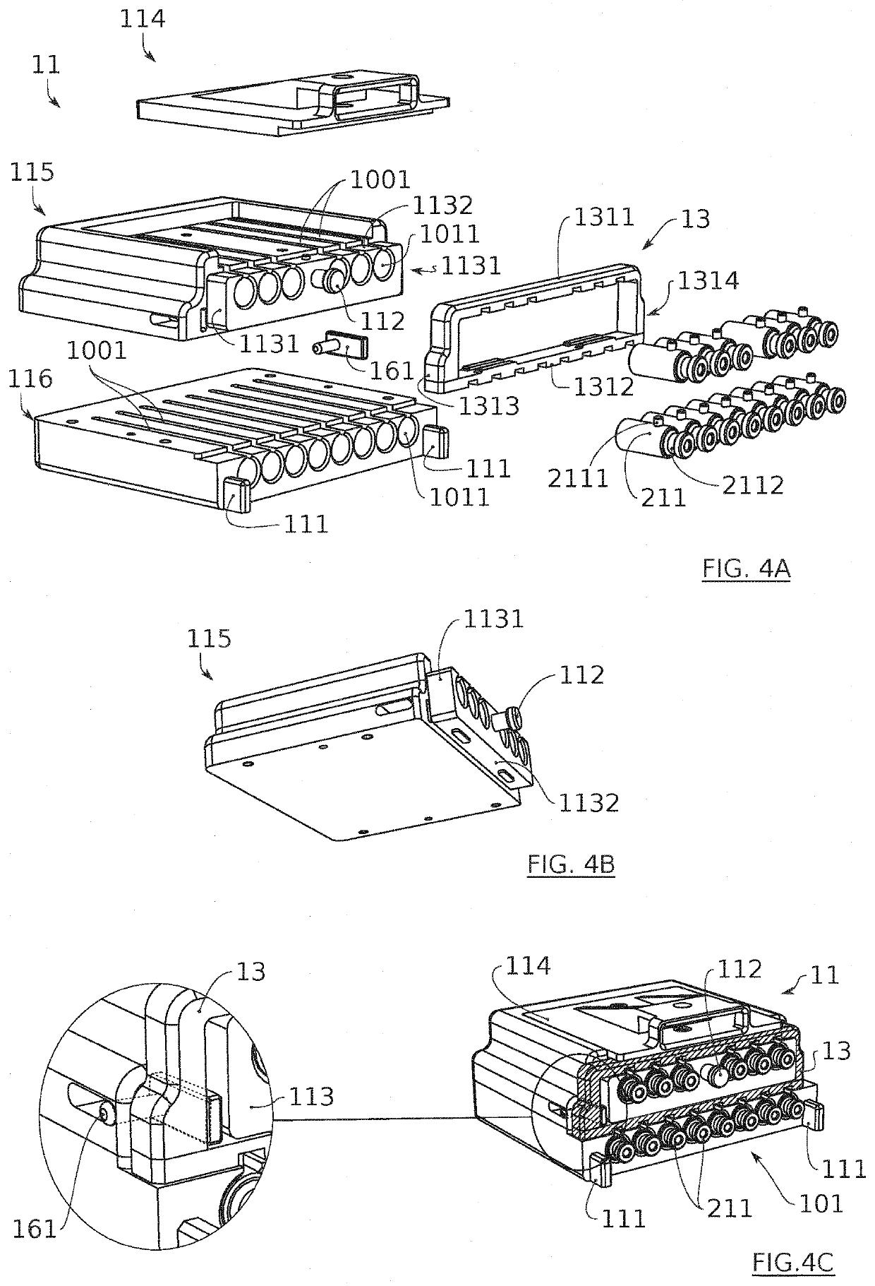
[0069]Regarding the connector according to the first aspect of the invention, it comprises a first block, constituting for example a male portion of the connector, and a second block, constituting for example a femal...


PUM


Abstract

The disclosure relates to the field of cabled robots and more particularly a connector for cables including a first block and a second block, the first and second blocks being configured to be connected together and to form, when they are connected together, a plurality of sliding guides in each of which a pair of first and second cables connected together at their respective first ends is intended for sliding, the connector further including a first locking component mounted on the first block so as to be movable between a locking position and a release position of the set of first ends of the first cables, and further including a second locking component mounted on the second block so as to be movable between a locking position and a release position of the set of first ends of the second cables.

Description

TECHNICAL FIELD[0001]The invention relates to the field of cabled robots. The invention more particularly relates to a connector for cables intended for equipping a cabled robot. It can be applied advantageously in the medical field, and in particular the field of interventional radiology, the latter consisting in particular in inserting needles into the body of a patient in order to take therefrom a sample or treat a tumour for example. However, its application can also be considered in the field of industrial robotics.PRIOR ART[0002]In reference to FIG. 1, a cabled robot 9 can be defined as a type of parallel manipulator wherein flexible cables 91, such as Bowden cables, are used as actuators. More particularly, an end of each cable can be wound around a rotor driven in rotation by a motor 92 and the other end can be connected to an instrument or instrument element 93, designed to interact with the environment. In the medical field, the instrument 93 can be a surgical tool, more o...

Claims


Application Information

Patent Timeline
IPC IPC(8): H01R13/436H01R13/629
CPCH01R13/4364A61B34/71H01R13/629A61B2090/508H01R2201/12
Inventor FOUARD, CELINELENFANT, JEREMYGANESARATNAM, GOKULARAJAHHUNGR, NIKOLAI
Owner UNIV GRENOBLE ALPES
Why Eureka
Try Eureka