Large-power motor hanging installation structure

An installation structure and motor technology, applied in the field of motors, can solve the problems of insufficient thread bearing capacity, affecting the use of equipment, and heavy motor weight, etc., and achieve the effects of increasing the stability of the equipment, enhancing the service life, and increasing the strength of components

Pending Publication Date: 2019-11-12
DALIAN YULIN ELECTRIC MOTOR
View PDF0 Cites 0 Cited by
  • Summary
  • Abstract
  • Description
  • Claims
  • Application Information

AI Technical Summary

Problems solved by technology

[0002] The installation of high-power motors generally adopts B3 (fixed with feet), but in special occasions and under the given conditions of the user, the B3 installation method cannot meet the user's requirements, so the B5 installation method will be used. The original B5 installation method is removed. The bearing sleeve of the original equipment is transformed into a bearing sleeve suitable for the installation of the motor. However, due to the heavy weight of the motor and the change of the original structure, the bearing capacity of the original thread is not enough, and there are installation deviations, which may cause local deformation of the equipment and cause the equipment to output in a short time. Shaft oil leakage affects the use of equipment

Method used


Image

  • Large-power motor hanging installation structure
  • Large-power motor hanging installation structure
  • Large-power motor hanging installation structure

Examples


Embodiment 1

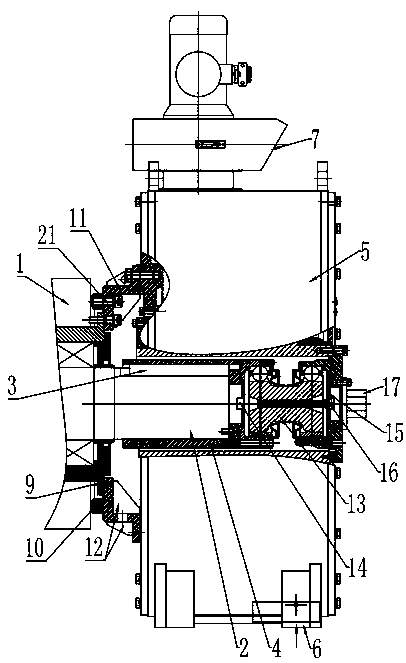
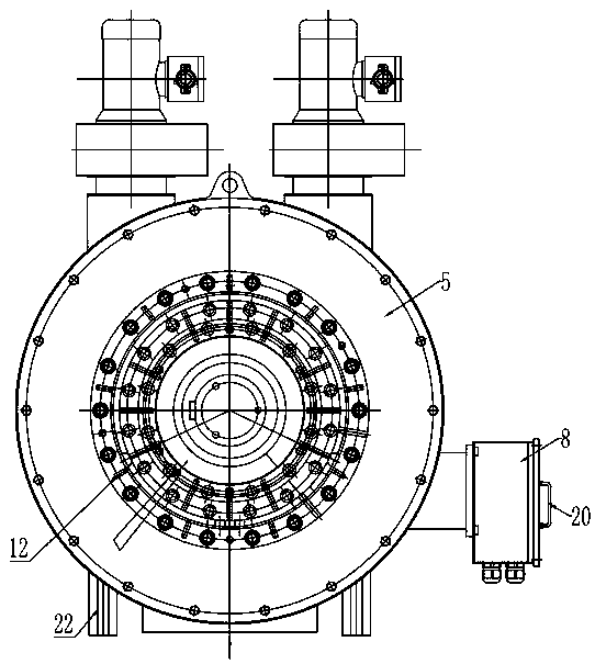
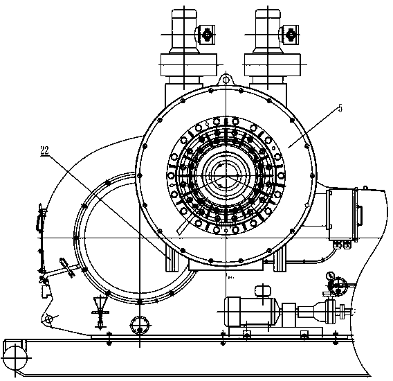
[0024] Embodiment 1: According to Figure 1-5 It can be seen that a high-power motor suspension installation structure includes a motor body 1 and an input shaft 2 arranged on the motor body 1. The input shaft 2 is provided with a shaft key 3 and a keyway matching the shaft key 3. The outer side of the input shaft 2 A shaft sleeve 4 is set in the sleeve, and the shaft sleeve 4 is covered with an organic base 5. An air inlet 6 is provided under the base 5, and external air can enter from the air inlet 6 from bottom to top. To the right, it is discharged from the air outlet 7. A junction box 8 is installed on the side wall of the machine base 5. An equipment bearing sleeve 9 is set on the side of the input shaft 2 close to the motor body 1. A fixing ring 10 is provided on the outside of the equipment bearing sleeve 9. The equipment bearing sleeve The centering flange 11 is fixedly connected to the outer circle of 9, and the centering flange 11 is positioned through the outer cir...

Embodiment 2

[0025] Embodiment 2: According to Figure 6-7 It can be seen that, in order to ensure the stability of the motor performance in the case of user-specific and large torque, B35 type installation can also be adopted, by adding feet under the process support 22 to form a foot connection, and the rest of the embodiments are the same as in Embodiment 1. same.


PUM


Abstract

The invention discloses a large-power motor hanging installation structure, and relates to the field of motors. The large-power motor hanging installation structure comprises a motor body and an inputshaft, wherein the input shaft is arranged on the motor body, a shaft key and a key groove are arranged in the input shaft, the key groove is matched with the shaft key, a shaft sleeve sleeves an outer side of the input shaft, a machine seat sleeves the shaft sleeve, a universal coupler is arranged at one end of the input shaft, and a manual disc axel is arranged at the other end of the universalcoupler. In the installation structure, the original structure of equipment is maintained only by an outer circle spigot and a threaded hole on the basis that an original equipment bearing sleeve structure is not changed, two layers of bolts are respectively fastened on an equipment shell and a fixed ring, the torque transmission is improved, and the equipment stability is improved; the other endof a motor centering flange is connected with a machine seat spigot in a positioning way, the screwing length of a connection part is thickened, and the bonding strength is improved; and by a dustproof device, dust can be effectively prevented from entering the motor, and a process support can be used for providing a stable foundation for transmission, disassembly and assembly.

Description

technical field [0001] The invention relates to the technical field of electric motors, in particular to a suspension installation structure for high-power electric motors. Background technique [0002] The installation of high-power motors generally adopts B3 (fixed with feet), but in special occasions and under the given conditions of the user, the B3 installation method cannot meet the user's requirements, so the B5 installation method will be used. The original B5 installation method is removed. The bearing sleeve of the original equipment is transformed into a bearing sleeve suitable for the installation of the motor. However, due to the heavy weight of the motor and the change of the original structure, the bearing capacity of the original thread is not enough, and there are installation deviations, which may cause local deformation of the equipment and cause the equipment to output in a short time. Shaft oil leakage affects the use of equipment. Contents of the inve...

Claims


Application Information

Patent Timeline
Patent Type & Authority Applications(China)
IPC IPC(8): H02K5/00H02K5/16H02K5/10H02K11/40H02K7/00
CPCH02K5/00H02K5/10H02K5/16H02K7/003H02K11/40
Inventor 林忠庆于永航孙雪
Owner DALIAN YULIN ELECTRIC MOTOR
Why Eureka
Try Eureka