
Exhaust gas aftertreatment device

a technology exhaust gas, which is applied in the direction of engines, mechanical equipment, machines/engines, etc., can solve the problems of increasing the complexity of exhaust gas aftertreatment, unable to ensure optimal exhaust gas aftertreatment, and small installation space, etc., to achieve the effect of short installation length

Pending Publication Date: 2022-04-07
VITESCO TECH GERMANY GMBH
View PDF12 Cites 0 Cited by
  • Summary
  • Abstract
  • Description
  • Claims
  • Application Information

AI Technical Summary

Benefits of technology

The present invention aims to create a device that optimizes the treatment of exhaust gas and filters out particles entrained in it. The device has a short installation length and minimizes pressure loss. The device includes a particle filter and a catalytically active substrate body, where the particle filter is positioned downstream of the substrate body to achieve high temperature and minimize pressure loss. An additional particle filter is positioned in the diverting region to increase overall particle separation and pre-filtering takes place to filter out large particles that might block the substrate body and reduce absorption in the annular filter, which in turn reduces pressure loss.

Problems solved by technology

Furthermore, in particular in the case of gasoline engines, there is an increasing problem with ultrafine exhaust-gas particles, such that the use of additional particle filters is now being considered in the case of gasoline engines too.
In particular with regard to the ever-increasing demands on the exhaust-gas aftertreatment and the ever more restrictive structural space requirements of the manufacturers, the arrangement of all of the components required for effective exhaust-gas aftertreatment poses an ever greater challenge.
A particular disadvantage of the devices in the prior art is that optimal exhaust-gas aftertreatment cannot be ensured if a particle filter is required in addition to the catalytic converter and the available installation space, in particular the installation length, is small.

Method used


Image

  • Exhaust gas aftertreatment device

Examples


Embodiment Construction

[0028]The following description of the preferred embodiment(s) is merely exemplary in nature and is in no way intended to limit the invention, its application, or uses.

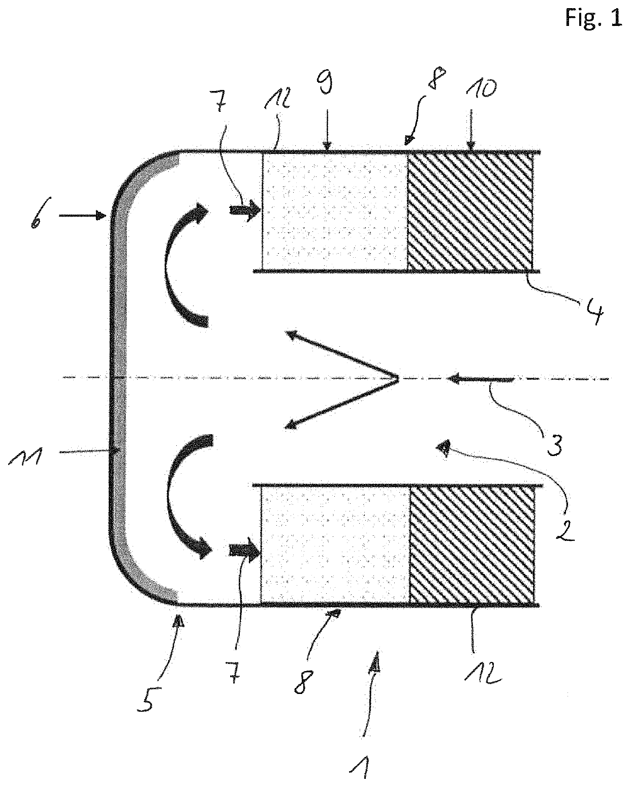
[0029]FIG. 1 shows an annular catalytic converter 1. This has a centrally situated first, tubular flow path 2 through which exhaust gas may flow along the throughflow direction 3. The tubular flow path 2 is delimited in the radial direction by an inner pipe 4. Arranged downstream of the tubular flow path 2 in the flow direction 3 is the diverting region 5.

[0030]The diverting region 5 is formed from a cover-like element 6, which is impinged on by the exhaust gas flowing through the tubular flow path 2. The impingement against the cover-like element 6 causes the exhaust gas to be diverted outward in the radial direction and finally directed in a flow direction 7 which is opposite to the throughflow direction 3 by 180 degrees.

[0031]The exhaust gas then flows through the second, annular flow path 8 through multiple elemen...


PUM


Abstract

A device for exhaust-gas aftertreatment, having a first, tubular flow path, having a diverting region and having a second, annular flow path. The tubular flow path is formed by an inner pipe and the annular flow path is, by an outer pipe running substantially parallel to the inner pipe, formed between the inner pipe and the outer pipe, and the diverting region is designed to divert the exhaust-gas flow from the tubular flow path into the annular flow path. The device has an annular catalytically active substrate body and an annular particle filter, wherein the substrate body and the particle filter are arranged in the annular flow path.

Description

CROSS-REFERENCE TO RELATED APPLICATIONS[0001]This application claims priority to PCT Application PCT / EP2020 / 067590, filed Jun. 24, 2020, which claims priority to German Patent Application No. DE 10 2019 209 303.5, filed Jun. 26, 2019. The disclosures of the above applications are incorporated herein by reference.FIELD OF THE INVENTION[0002]The invention relates to a device for exhaust-gas aftertreatment, having a first, tubular flow path, having a diverting region and having a second, annular flow path, wherein the tubular flow path is formed by an inner pipe and the annular flow path is, by an outer pipe running substantially parallel to the inner pipe, formed between the inner pipe and the outer pipe, and the diverting region is designed to divert the exhaust-gas flow from the tubular flow path into the annular flow path.BACKGROUND OF THE INVENTION[0003]For the exhaust-gas aftertreatment of exhaust gases of internal combustion engines, use is made inter alia of catalytic converter...

Claims


Application Information

Patent Timeline
Patent Type & Authority Applications(United States)
IPC IPC(8): F01N3/28F01N3/035F01N13/00
CPCF01N3/2892F01N3/035F01N2240/20F01N2250/02F01N2470/24F01N13/0097F01N3/021F01N3/20F01N2470/22Y02T10/12
Inventor BRÜCK, ROLFHIRTH, PETERSCHEPERS, SVENODENTHAL, DAVID
Owner VITESCO TECH GERMANY GMBH
Learn More