
Electro-mechanical brake device and method of controlling the same

a technology of electronic brake and actuator, which is applied in the direction of braking system, vehicle sub-unit features, transportation and packaging, etc., can solve the problems of increasing the number of connector pins included in the wcu, complicating the connection structure, and increasing the time required for initializing the ecu and the actuator of the emb, so as to reduce the number of connector pins and simplify the connection structure

Pending Publication Date: 2022-04-14
HYUNDAI MOBIS CO LTD
View PDF0 Cites 0 Cited by
  • Summary
  • Abstract
  • Description
  • Claims
  • Application Information

AI Technical Summary

Benefits of technology

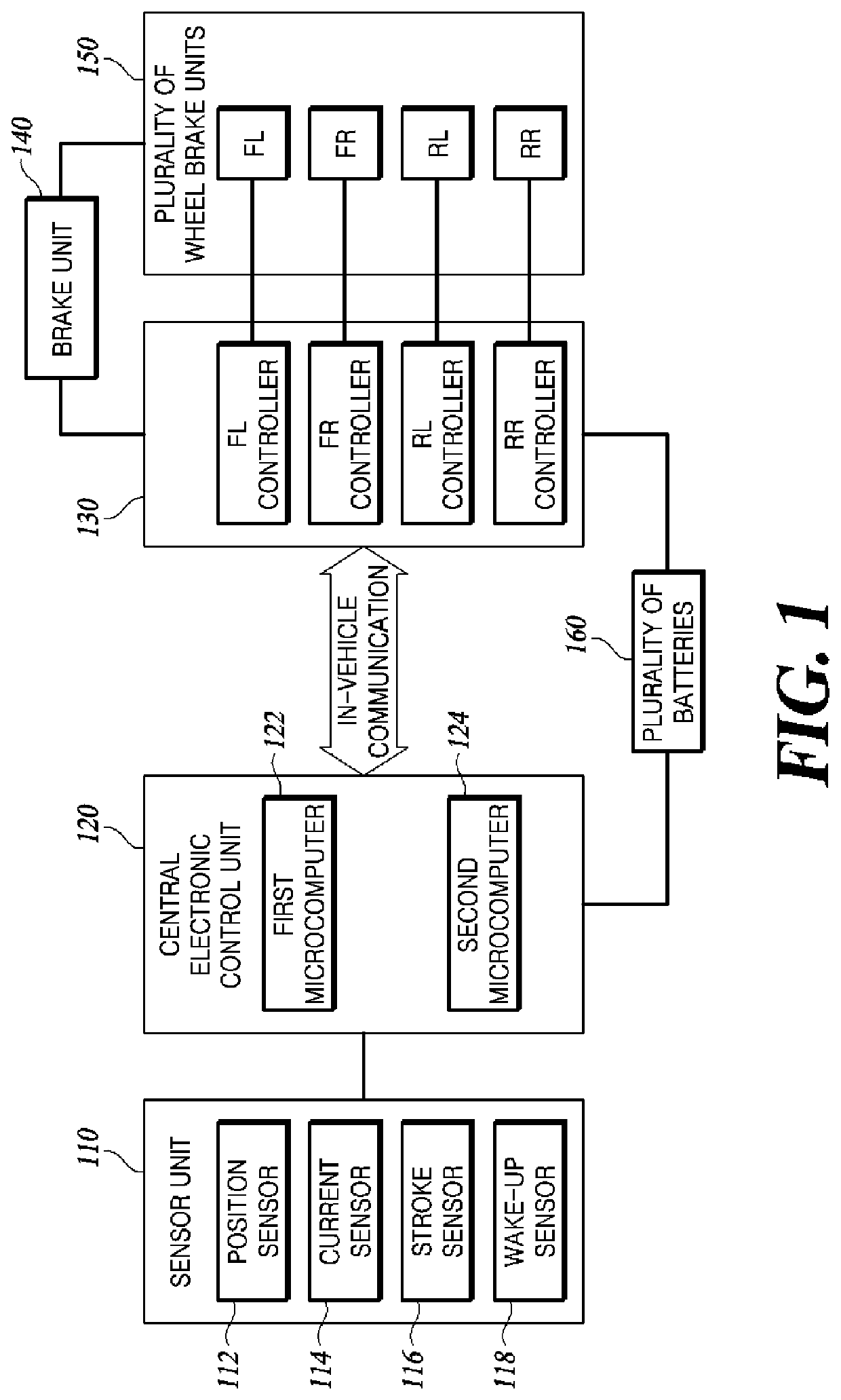
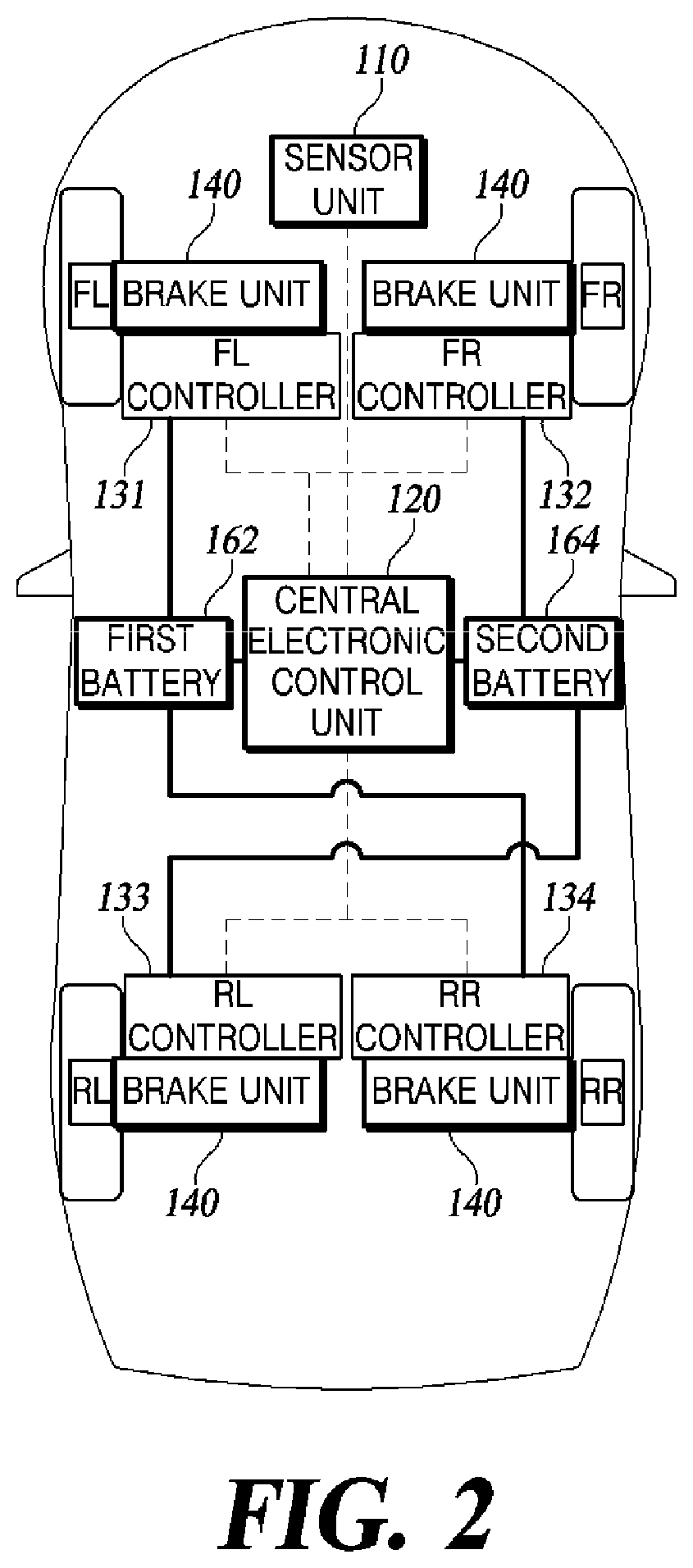
This patent aims to reduce the number of connector pins and simplify the connection structure of a vehicle's electronic control unit (ECU) by using a single signal to activate multiple electronic control units (ECUs). By utilizing in-vehicle communication, the central ECU can activate a wheel ECU without the need for individual wires or separate pins. This also simplifies the initialization of electro-mechanical brakes (EMBs) and reduces the time required to achieve initial braking performance. Overall, this technology streamlines the vehicle's electronics system and improves overall efficiency.

Problems solved by technology

However, when the wake-up sensor is connected to the WCU, there are problems of increasing the number of connector pins included in the WCU and complicating a connection structure.
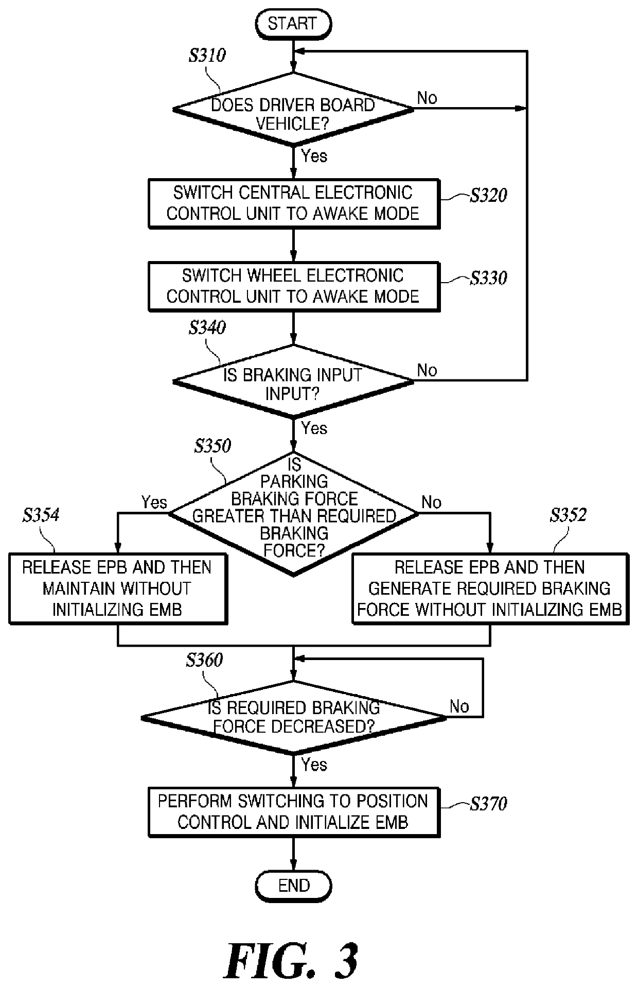
However, there is a problem in that the time required for initializing the ECU and the actuator of the EMB is increased, and furthermore, there is a problem in that a delay occurs when the EMB generates a braking force.

Method used


Image

  • Electro-mechanical brake device and method of controlling the same
  • Electro-mechanical brake device and method of controlling the same
  • Electro-mechanical brake device and method of controlling the same

Examples


Embodiment Construction

[0015]Hereinafter, some exemplary embodiments of the present disclosure will be described in detail with reference to the accompanying drawings. In the following description, like reference numerals preferably designate like elements, although the elements are shown in different drawings. Further, in the following description of some embodiments, a detailed description of known functions and configurations incorporated therein will be omitted for the purpose of clarity and for brevity.

[0016]Additionally, various terms such as first, second, A, B, (a), (b), etc., are used solely to differentiate one component from the other but not to imply or suggest the substances, order, or sequence of the components. Throughout this specification, when a part ‘includes’ or ‘comprises’ a component, the part is meant to further include other components, not to exclude thereof unless specifically stated to the contrary. The terms such as ‘unit’, ‘module’, and the like refer to one or more units for ...


PUM


Abstract

A method of controlling an electro-mechanical brake device, includes: switching a central electronic control unit (ECU) to an awake mode based on a wake-up signal; transmitting a signal such that a wheel ECU is switched from a sleep mode to the awake mode; when a braking input is detected, supplying a current to a motor mounted on an electro-mechanical brake (EMB) using current control to generate a braking force; when a parking braking force is less than a required braking force, controlling the wheel ECU to release the parking braking force and generate the required braking force, and when the parking braking force is greater than or equal to the required braking force, releasing the parking braking force and maintaining the braking force generated in a wheel; when the braking force reaches the required braking force or the braking force is maintained, switching the current control to position control.

Description

CROSS-REFERENCE TO RELATED APPLICATION[0001]Tis application claims priority to and the benefit of Korean Patent Application No. 10-2020-0132249, filed on Oct. 13, 2020, the disclosure of which is incorporated herein by reference in its entirety.BACKGROUND1. Technical Field[0002]Embodiments of the present disclosure relate to an electro-mechanical brake device and a method of controlling the same.2. Discussion of Related Art[0003]The content described in this section merely provides background information about the present disclosure and does not constitute the related art.[0004]Electro-mechanical brakes (EMBs) have been developed and widely used. Although the EMB has been developed to be used as an electronic parking brake (EPB), recently, as the EMB has been used for main braking by replacing the conventional hydraulic brake, a use area thereof has been expanded. The EMB is a device in which an actuator driven by a motor is mounted on a brake caliper to directly brake a vehicle wit...

Claims


Application Information

Patent Timeline
IPC IPC(8): B60T8/17B60T13/74
CPCB60T8/17F16D2065/386B60T2220/04B60T13/741B60T7/042B60T13/662B60T13/74B60T8/322B60R16/023B60Y2400/81B60Y2400/82
Inventor KIM, JONG SUNG
Owner HYUNDAI MOBIS CO LTD
Learn More