Vibration damping device for elevator rope and elevator apparatus
- Summary
- Abstract
- Description
- Claims
- Application Information
AI Technical Summary
Benefits of technology
Problems solved by technology
Method used
Image
Examples
first embodiment
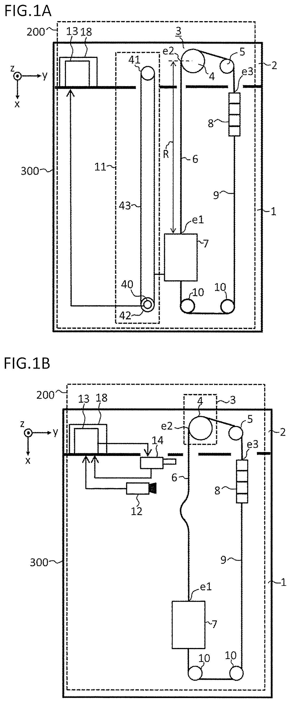
[0038]FIG. 1 are schematic views of an elevator apparatus according to a first embodiment of the present invention. In FIG. 1(a) and FIG. 1(b), an x-axis, a y-axis, and a z-axis in a 3-axis orthogonal coordinate system are illustrated. The x-axis is set in parallel to a portion of a vibration damping range R of main ropes 6, and a vertically downward direction thereof is a positive direction of the x-axis. Both of FIG. 1(a) and FIG. 1(b) are illustrations of an elevator apparatus 200.
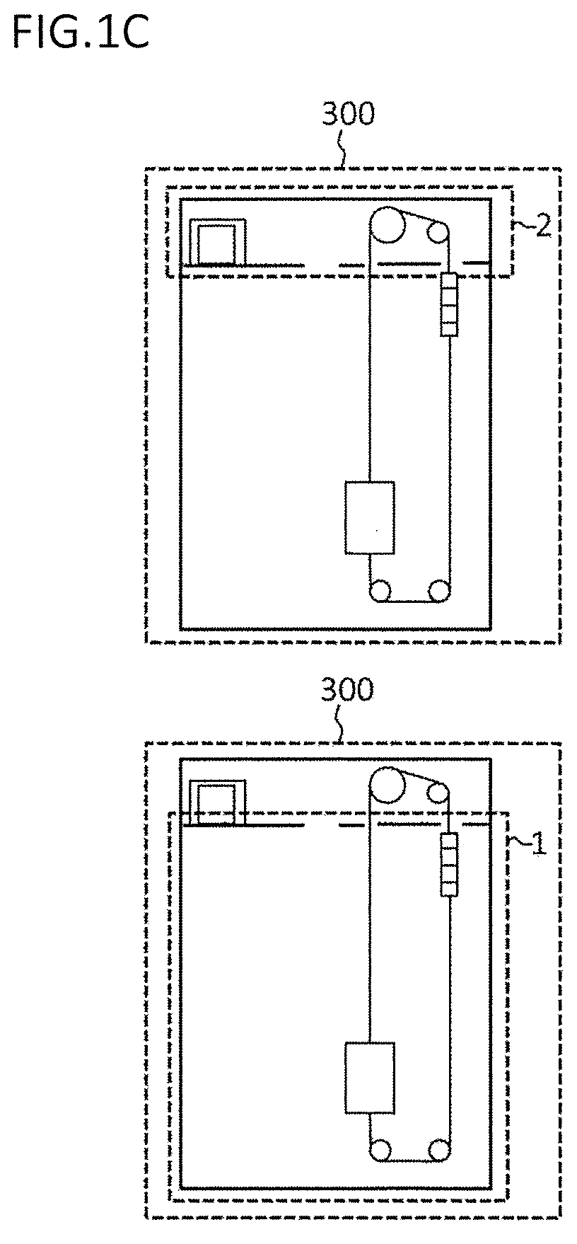
[0039]To simplify the illustration, a car position measuring unit 11 is illustrated in FIG. 1(a), and a lateral vibration measuring unit 12 and an actuator 14 are illustrated in FIG. 1(b). In FIG. 1(a), the lateral vibration measuring unit 12 and the actuator 14 are not illustrated. Moreover, in FIG. 1(b), the car position measuring unit 11 is not illustrated. In FIG. 1(c), two schematic views of the elevator apparatus are illustrated, and arrangement of a building 300, a hoistway 1, and a machine room ...
second embodiment
[0163]A vibration damping device for an elevator rope according to a second embodiment includes a building shake detection unit configured to detect a shake of a building. FIG. 11 are schematic views of an elevator apparatus according to the second embodiment of the present invention, the elevator apparatus including an accelerometer. In a description regarding FIG. 11 to FIG. 13, a description of portions in each of which a configuration and an operation are the same as those in the configuration of the first embodiment is omitted.
[0164]Components illustrated in FIG. 11 are included in the elevator apparatus 200a, except fora building 300a and also a hoistway 1a and a machine room 2a being parts of the building 300a. Moreover, a vibration damping device 100a for an elevator rope is a part of the elevator apparatus 200a.
[0165]In FIG. 11(a) and FIG. 11(b), an x-axis, a y-axis, and a z-axis in a 3-axis orthogonal coordinate system are illustrated. The x-axis is set in parallel to a p...
third embodiment
[0206]A vibration damping device for an elevator rope according to a third embodiment includes a weighing device in addition to the components of the vibration damping device for an elevator rope, which is disclosed in the first embodiment.
[0207]FIG. 14 are schematic views of an elevator apparatus according to the third embodiment of the present invention. Structures and operations of an elevator apparatus 200c and a vibration damping device 100c for an elevator rope, which are not disclosed in the third embodiment, are the same as the structures and operations of the elevator apparatus 200 and the vibration damping device 100 for an elevator rope, which are disclosed in the first embodiment.
[0208]Components illustrated in FIG. 14 are included in the elevator apparatus 200c, except fora building 300c and also a hoistway 1c and a machine room 2c being parts of the building 300c. Moreover, the vibration damping device 100c for an elevator rope is a part of the elevator apparatus 200c....
PUM
 Abstract
Description
Claims
Application Information
 - R&D
- Intellectual Property
- Life Sciences
- Materials
- Tech Scout
- Unparalleled Data Quality
- Higher Quality Content
- 60% Fewer Hallucinations
Browse by: Latest US Patents, China's latest patents, Technical Efficacy Thesaurus, Application Domain, Technology Topic, Popular Technical Reports.
© 2025 PatSnap. All rights reserved.Legal|Privacy policy|Modern Slavery Act Transparency Statement|Sitemap|About US| Contact US: help@patsnap.com


