Optical system for imaging an object and method for operating said optical system

Active Publication Date: 2017-04-18
CARL ZEISS SMT GMBH
View PDF20 Cites 0 Cited by
  • Summary
  • Abstract
  • Description
  • Claims
  • Application Information

AI Technical Summary

Benefits of technology

The optical system described in this patent has two main benefits. Firstly, it compensates for delayed movement caused by inertia by shifting forward the phase of a high-frequency control signal. Secondly, it increases the amplitude of this control signal to compensate for the reduction in amplitude due to inertia. To achieve this, a limit frequency and a factor are established prior to the operation of the optical system. By using this optical system, closed-loop control can be dispensed with, saving energy. However, even if closed-loop control is provided, it would only compensate for smaller deviations from the predetermined actuation curve. This means that only small movements are required for compensation, leading to low energy consumption.

Problems solved by technology

The image captured by an observer through the telescope or the field glasses is often perceived to be shaking because trembling movements or rotational movements of the hands of the user, and also movements underfoot, in turn cause movements of the optical system.
As a result of the inertia of the mass of the image stabilizing unit or of the optical element of the image stabilizing unit, there is, in this case, a time delay between the initiation of the movement by the actuation signal in the drive units and the implementation of the actual movement of the image stabilizing unit or of the optical element of this image stabilizing unit.
A further disadvantage of the aforementioned inertia is that the amplitude of the movement of the image stabilizing unit or of the optical element of the image stabilizing unit becomes smaller with increasing frequency.
In order to be able to react to deviations from an intended value of an actuation signal, an excessively strong drive unit is used as a result of the above-described inertia problem.
However, a drive unit with such a design requires much energy and installation space.
Furthermore, it was found oscillatory phenomena occur in the case of the fast closed-loop control by means of the PID control which, firstly, reduce the quality of the image stabilization and, secondly, likewise increase the energy consumption.

Method used


Image

  • Optical system for imaging an object and method for operating said optical system
  • Optical system for imaging an object and method for operating said optical system
  • Optical system for imaging an object and method for operating said optical system

Examples


Embodiment Construction

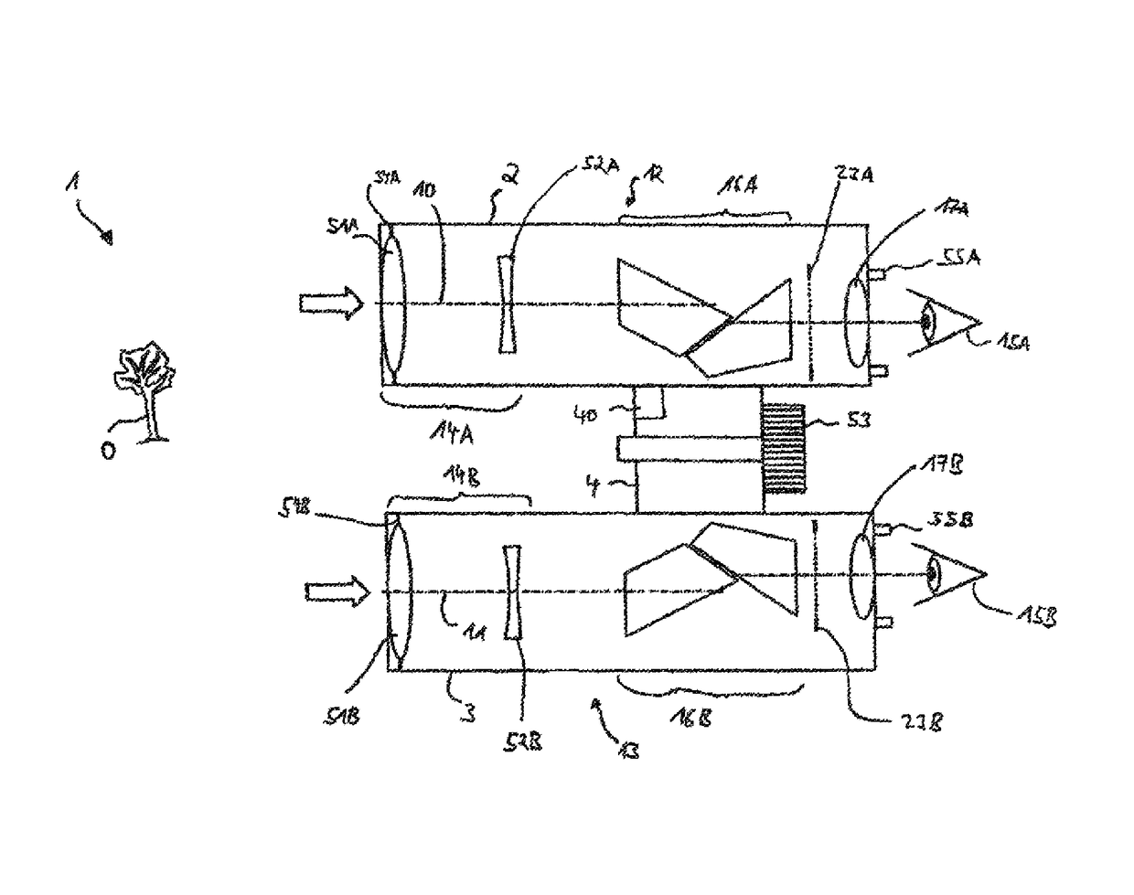
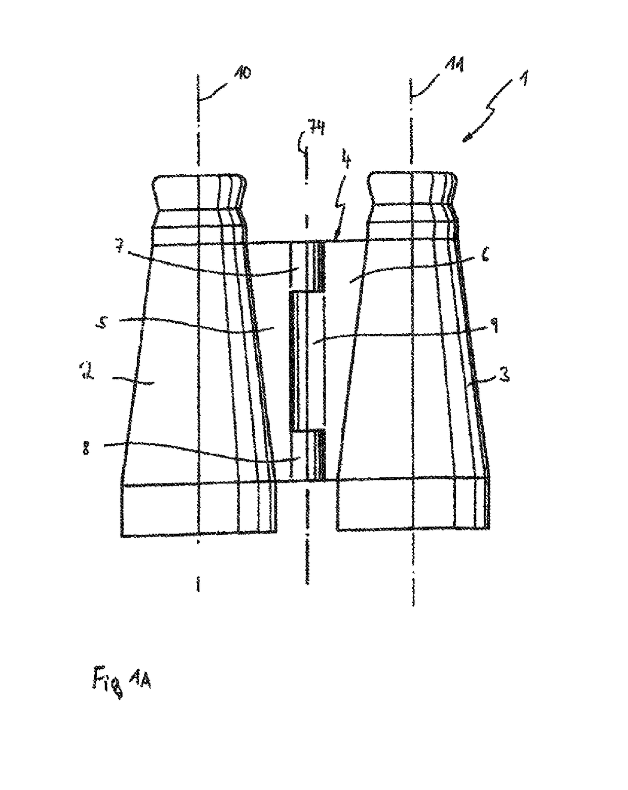
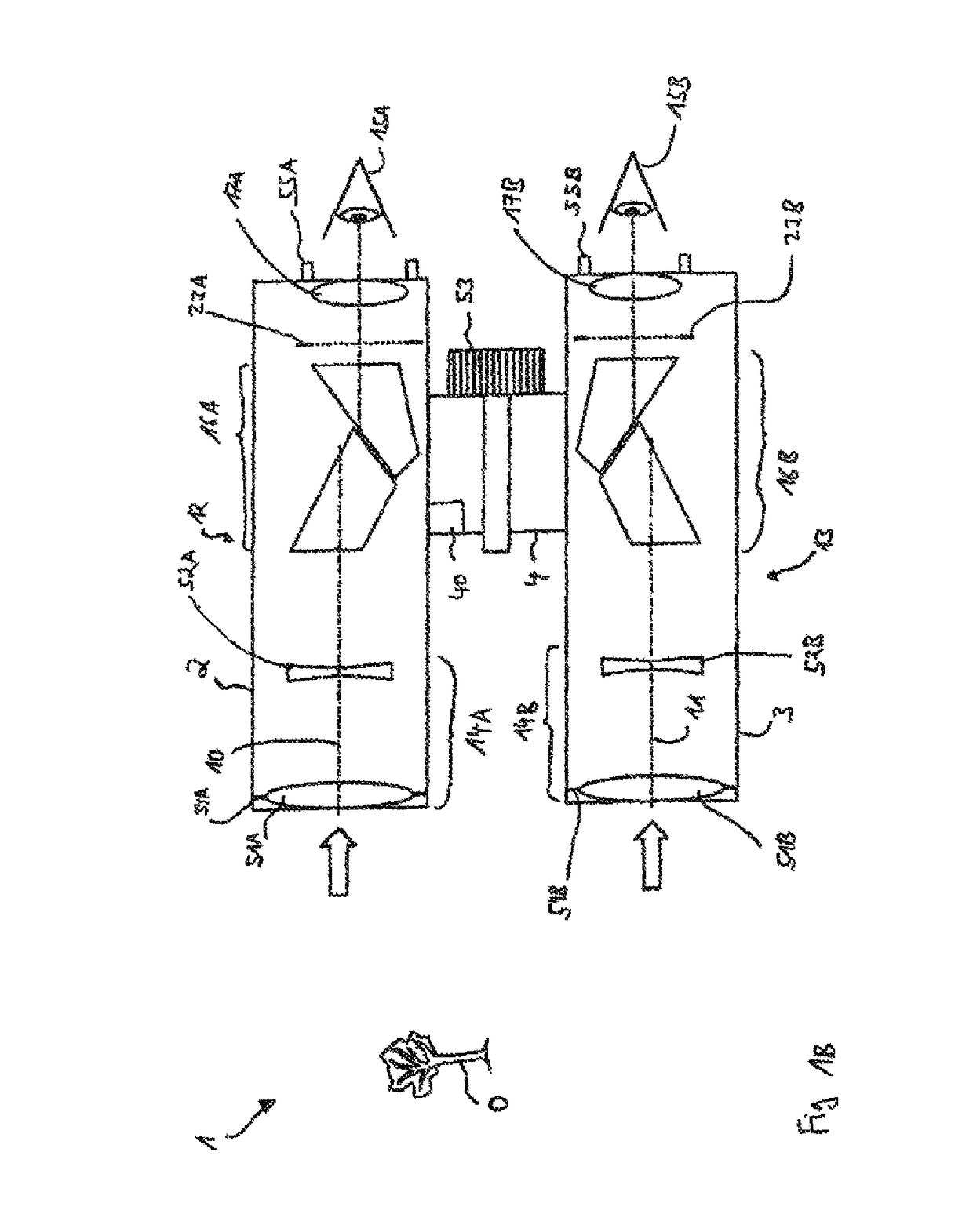
[0069]FIG. 1A shows a first schematic illustration of the field glasses 1, which have a tube-shaped first housing part 2 and a tube-shaped second housing part 3. A first optical axis 10 extends through the first housing part 2. By contrast, a second optical axis 11 extends through the second housing part 3. The first housing part 2 is connected to the second housing part 3 by means of a folding bridge 4. The folding bridge 4 has a first hinge part 5, which is formed onto the first housing part 2. Furthermore, the folding bridge 4 has a second hinge part 6, which is arranged on the second housing part 3. The first hinge part 5 has a first holding part 7 and a second holding part 8, between which a third holding part 9 of the second hinge part 6 is arranged. An axle pin (not illustrated) extends through the first holding part 7, the second holding part 8 and the third holding part 9 such that the relative position of the first housing part 2 and the second housing part 3 can be set wi...


PUM


Abstract

An optical system for imaging an object includes a objective, an image stabilizing unit, an image plane and a drive unit, which is arranged at the image stabilizing unit and provided for moving the image stabilizing unit. The optical system includes a control unit. A signal from the control unit is forwarded to a first high-pass filter. The control unit has an output line and the high-pass filter has a filter output line. Both the output line and the filter output line are arranged at an addition unit such that an actuation signal from the control unit and an output signal from the high-pass filter are added to produce an addition signal. The addition unit is arranged at the drive unit in such a way that the addition signal is used for actuating the drive unit and for moving the image stabilizing unit.

Description

TECHNICAL FIELD[0001]The system described herein relates to an optical system for imaging an object and to a method for operating said optical system.BACKGROUND OF THE INVENTION[0002]Optical systems may be used, for example, in a telescope or in field glasses. By way of example, optical systems in the form of field glasses are known, which have two housings in the form of two tubes. A first imaging unit having a first optical axis is arranged in a first tube. A second imaging unit having a second optical axis is arranged in a second tube. Moreover, the prior art has disclosed field glasses which have a first housing in the form of a first tube with a first optical axis and a second housing in the form of a second tube with a second optical axis. The first housing is connected to the second housing by way of a folding bridge, with the folding bridge having a first hinge part arranged at the first housing and the folding bridge having a second hinge part arranged at the second housing...

Claims


Application Information

Patent Timeline
IPC IPC(8): G02B27/64G02B26/08G02B23/02
CPCG02B26/0883G02B27/646G02B23/02G03B2205/0007
Inventor BACH, CHRISTIAN
Owner CARL ZEISS SMT GMBH
Why Eureka
Try Eureka