Differential transmission line with common mode suppression

Inactive Publication Date: 2018-02-01
KEYSIGHT TECH
View PDF2 Cites 2 Cited by
  • Summary
  • Abstract
  • Description
  • Claims
  • Application Information

AI Technical Summary

Benefits of technology

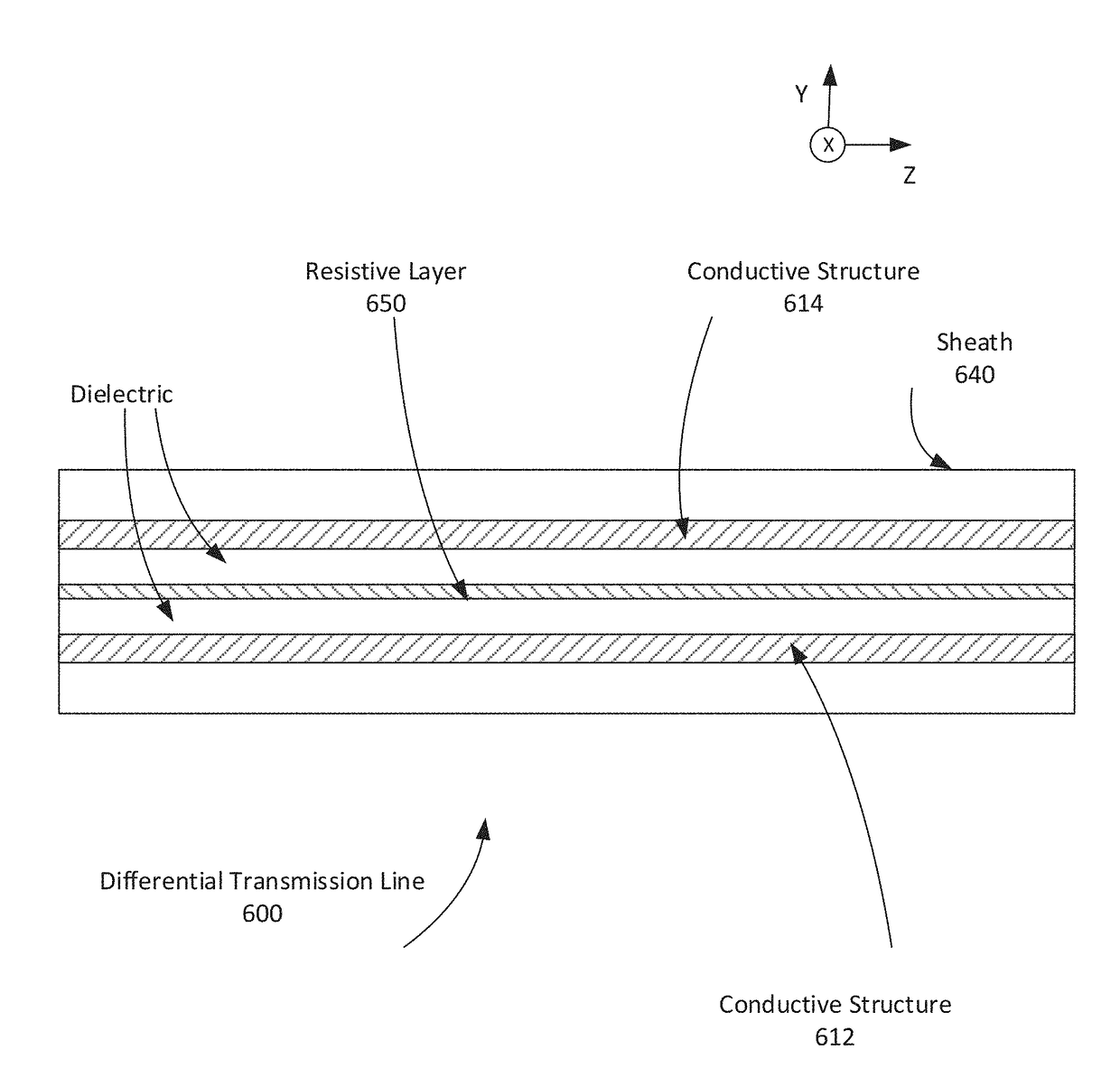
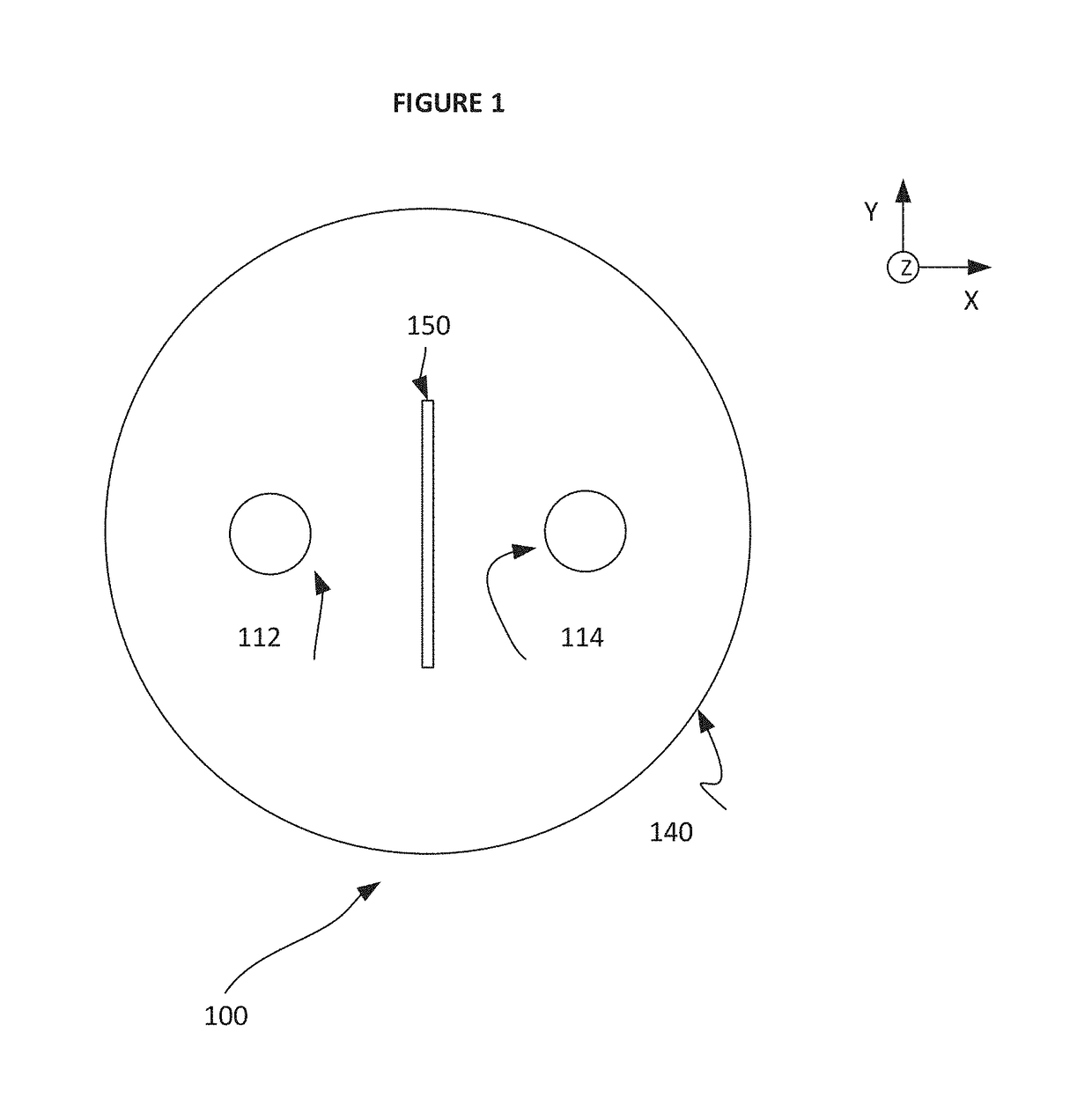
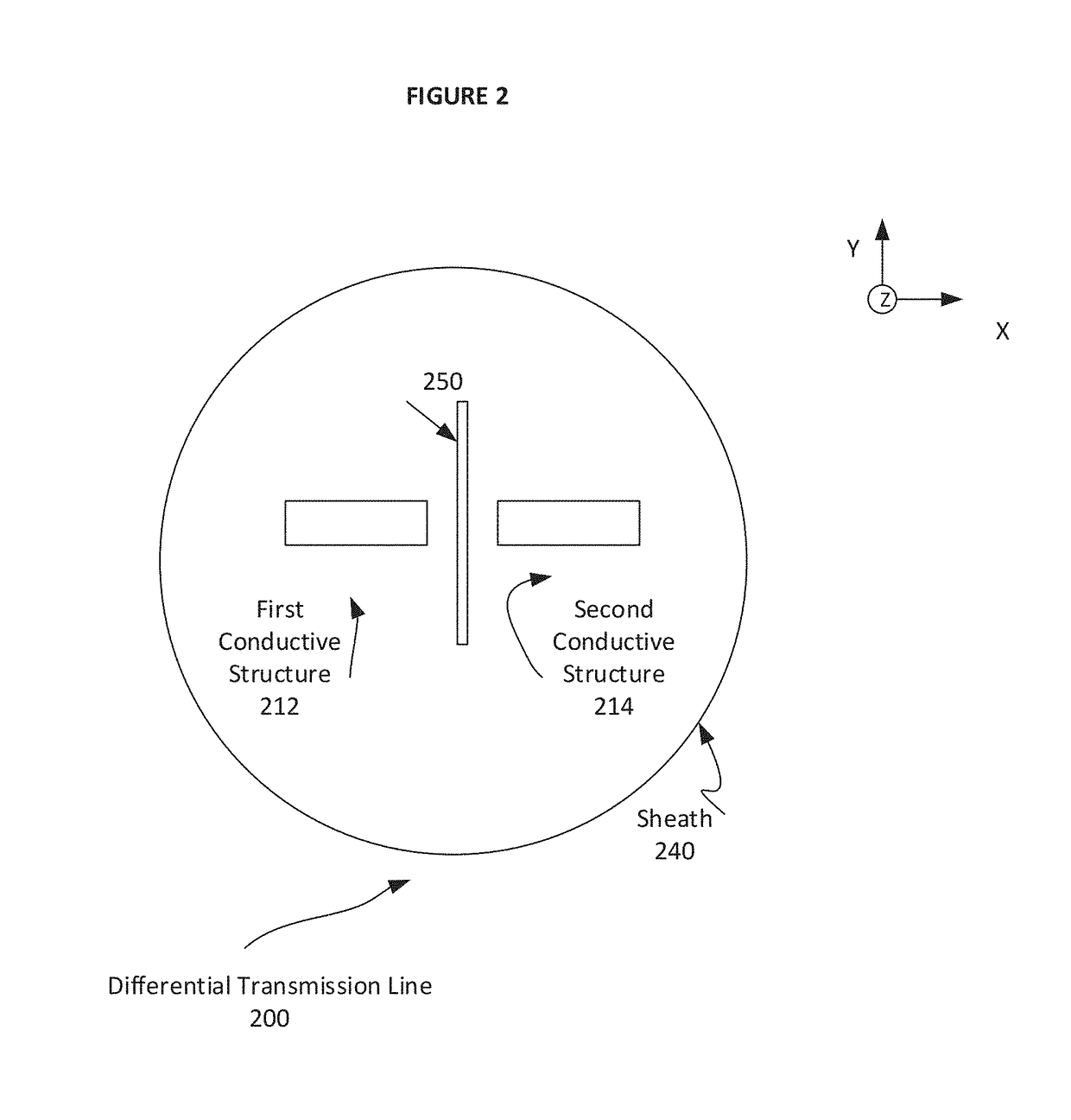
The present patent relates to a differential electromagnetic transmission line with a resistive layer for common mode suppression. The technical effect of this invention is to improve the signal fidelity and reduce interference in electronic circuits, particularly in high-speed and high-voltage applications, by suppressing the undesirable modes of signals. The invention uses selective filters to suppress the undesirable mode signals and all-pass filters for the desirable mode signals. The invention also includes an interior cross section of the differential transmission line with common mode suppression for reference. The patent text provides various methods for designing and analyzing the differential transmission line with common mode suppression.

Problems solved by technology

Differential signaling has costs too, and does not work perfectly in practice.
For example, a single mode of signal propagation is typically desirable for electromagnetic signals, as multi-mode signal propagation may result in non-idealities due to coupling (interference) between signal components of the different modes.

Method used


Image

  • Differential transmission line with common mode suppression
  • Differential transmission line with common mode suppression
  • Differential transmission line with common mode suppression

Examples


Embodiment Construction

[0031]In the following detailed description, for purposes of explanation and not limitation, representative embodiments disclosing specific details are set forth in order to provide a thorough understanding of the present teachings. Descriptions of known systems, devices, materials, methods of operation and methods of manufacture may be omitted so as to avoid obscuring the description of the example embodiments. Nonetheless, systems, devices, materials and methods that are within the purview of one of ordinary skill in the art may be used in accordance with the representative embodiments.

[0032]It is to be understood that the terminology used herein is for purposes of describing particular embodiments only, and is not intended to be limiting. The defined terms are in addition to the technical and scientific meanings of the defined terms as commonly understood and accepted in the technical field of the present teachings.

[0033]It will be understood that, although the terms first, secon...


PUM


Abstract

A differential transmission line includes a sheath, a first conductive structure, a second conductive structure, and a resistive layer. The first conductive structure is disposed along the differential transmission line and within the sheath, and contributes to formation of a three-dimensional electromagnetic field. The second conductive structure is disposed along the differential transmission line and within the sheath, and contributes to formation of the three-dimensional electromagnetic field. The resistive layer is aligned to be substantially perpendicular to an electric field component of a first mode of the three-dimensional electromagnetic field, and to provide absorption of an electric field component of a second mode of the three-dimensional electromagnetic field.

Description

BACKGROUND1. Field of the Disclosure[0001]The present disclosure relates to the field of differential electromagnetic transmissions. More particularly, the present disclosure relates to a differential electromagnetic transmission line with a resistive layer.2. Background Information[0002]In modern electronics, differential signals are often used to improve signal fidelity (signal to noise ratio). Differential signaling is used in a variety of settings, including:[0003]high speed digital circuits[0004]analog / radio frequency circuits[0005]high speed computation and communications equipment[0006]high voltage circuits[0007]For computation and communications equipment, differential signaling (e.g., using a serializer / deserializer) is used to address a clock skew issue. In analog and radio frequency equipment, differential signaling reduces sensitivity to electromagnetic interference. For high voltage circuits, differential signaling can be used because both transmission mechanisms can be...

Claims


Application Information

Patent Timeline
IPC IPC(8): H03H7/42H01P3/08
CPCH01P3/088H03H7/427H01P3/081H05K1/0216H05K1/0245H05K1/025H05K1/02H05K1/0234
Inventor MARSHALL, TODD STEVENVOOK, DIETRICH W.BANEY, DOUGLAS
Owner KEYSIGHT TECH
Why Eureka
Try Eureka