

Method for counteracting longitudinal oscillations of magnetic tape in a tape drive system
- Summary
- Abstract
- Description
- Claims
- Application Information
AI Technical Summary
Benefits of technology
Problems solved by technology
Method used
Image

Examples
Embodiment Construction
)
[0029]Detailed embodiments of the present invention are disclosed herein; however, it is to be understood that the disclosed embodiments are merely exemplary of the invention that may be embodied in various and alternative forms. The figures are not necessarily drawn to scale, some features may be exaggerated or minimized to show details of particular components. Therefore, specific structural and functional details disclosed herein are not to be interpreted as limiting, but merely as a representative basis for the claims and / or as a representative basis for teaching one skilled in the art to variously employ the present invention.
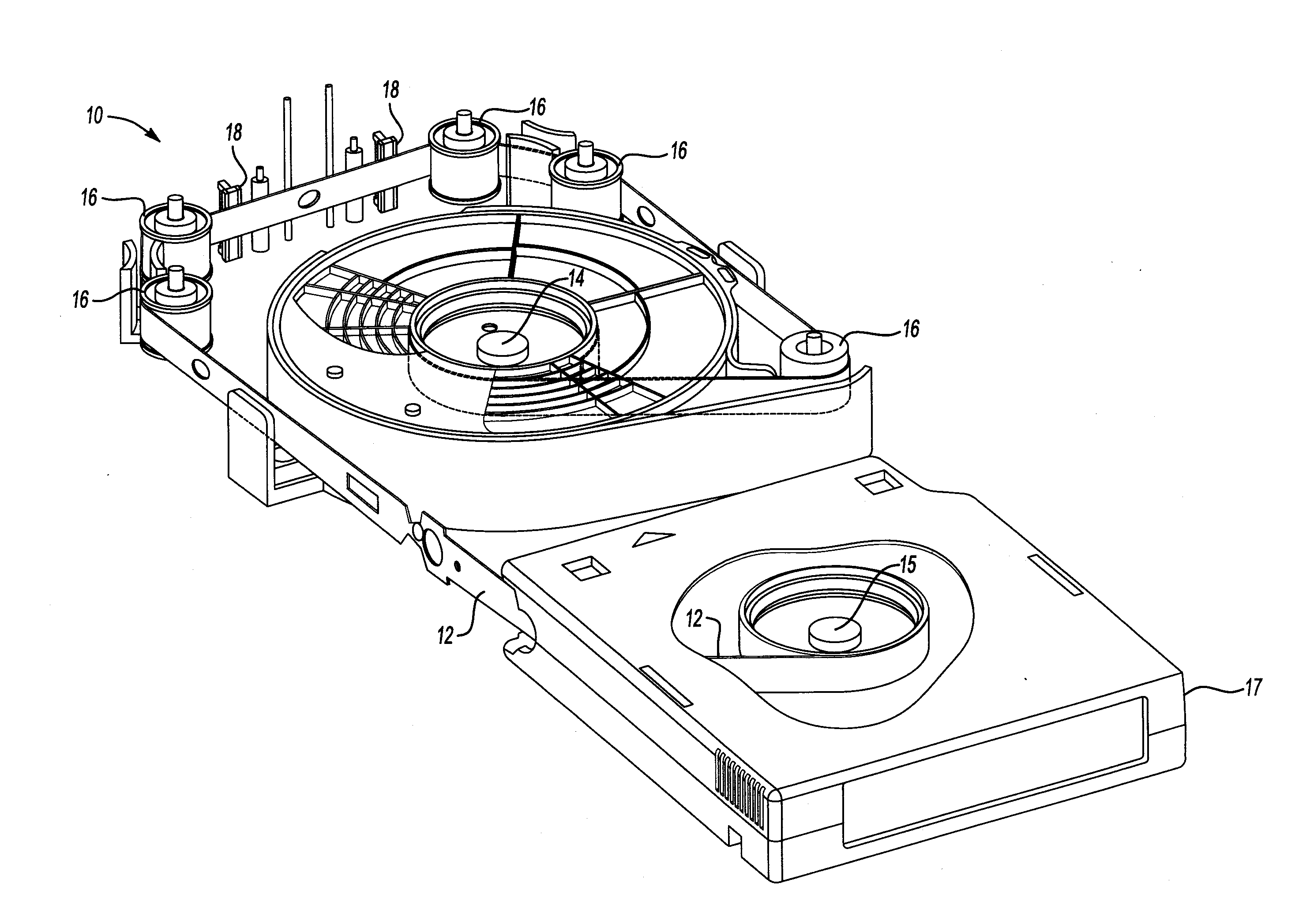
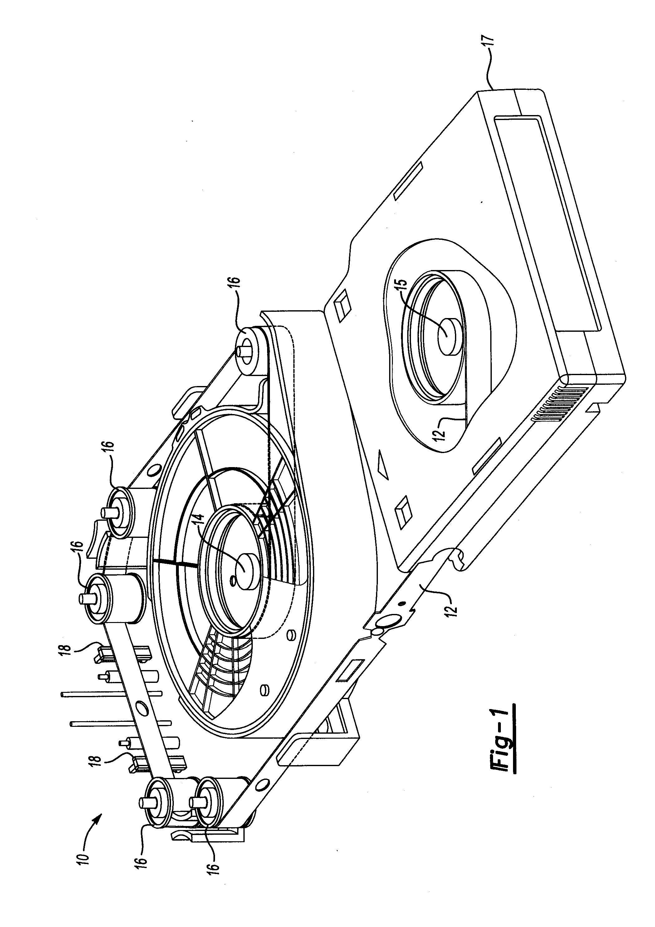
[0030]FIG. 1 is a perspective fragmentary view illustrating a portion of a tape drive system 10 capable of reading information from, and writing information to, a magnetic tape 12. Such tape drive systems are typically associated with computer tape backup systems. However, it should be understood that the teachings of the present invention are not limited...
PUM
 Abstract
Description
Claims
Application Information