
Tiltable chair

a tilting chair and seat technology, applied in the field of tilting chairs, can solve the problems of high cost, large number of parts, and poor tilting effect, and achieve the effects of preventing noise generation, enhancing elastic displacement, and improving tilting effectiveness

Active Publication Date: 2022-04-28
CHAIR MEISTER
View PDF0 Cites 2 Cited by
  • Summary
  • Abstract
  • Description
  • Claims
  • Application Information

AI Technical Summary

Benefits of technology

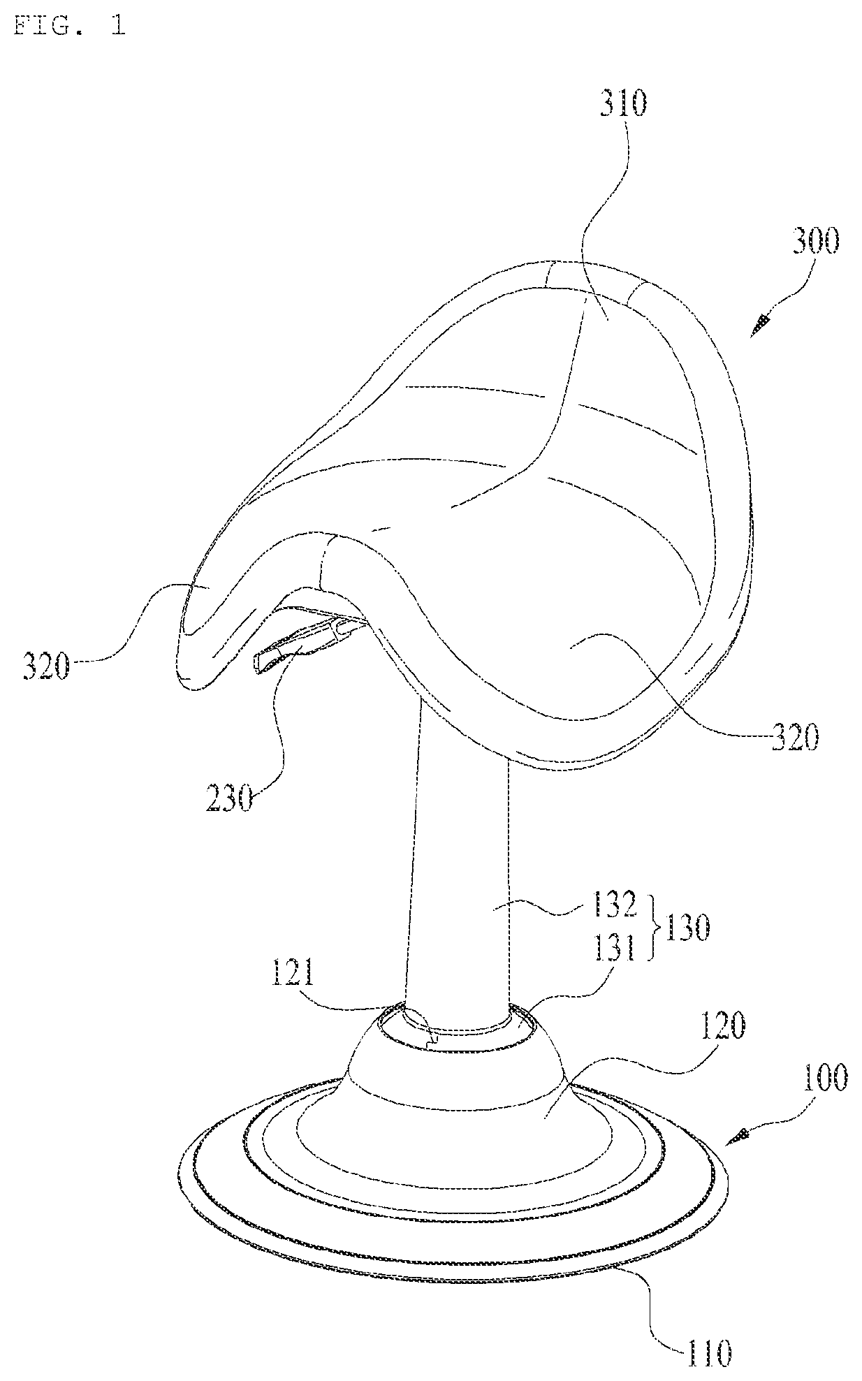
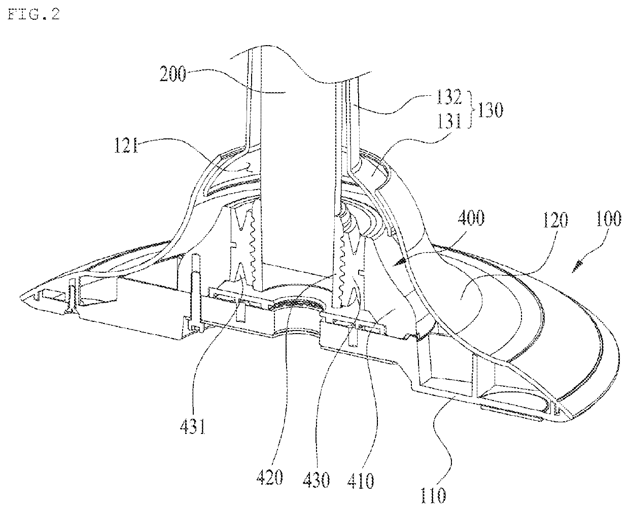
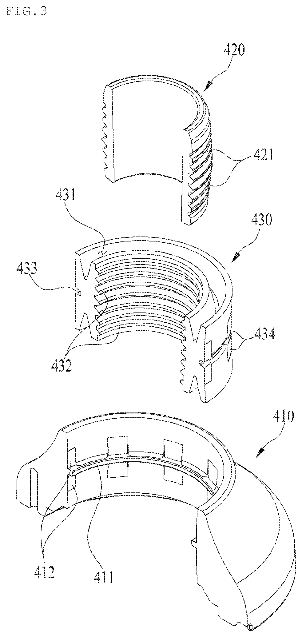
The present invention is a tiltable chair that uses an elastic tilting member instead of a complicated coil spring structure. This simplifies the chair design and reduces noise during tilting. The chair also has waveform coupling portions and a coupling groove that enhance the elastic displacement and increase fixing forces. Additionally, a tilt regulation plate is included for stability and efficient regulation of the gas cylinder's tilt angle.

Problems solved by technology

However, tiltable chair of the prior art has the first swinging link and the second swinging link as common parts thereof and has six coil springs, so that the chair provides different senses of tilting according to tilting directions, is complicated in configuration, has a large number of parts, and is expensive.
Besides, undesirably, the coil springs cause severe noise in a process of repeated tension and compression.

Method used


Image

  • Tiltable chair
  • Tiltable chair
  • Tiltable chair

Examples


Embodiment Construction

[0028]Hereinafter, an explanation on a tiltable chair according to the present invention will be in detail given with reference to the attached drawings.

[0029]For reference, terms and words used in the present specification and claims are not to be construed as being limited to their usual or dictionary meanings, and should be interpreted as a meaning and concept consistent with the technical idea of the present invention based on the principle that the inventor can appropriately define the concept of terms in order to describe the invention in the best way.

[0030]The present invention can be modified in various ways and can have several exemplary embodiments. Specific exemplary embodiments of the present invention are illustrated in the drawings and described in detail in the detailed description. However, this does not limit the invention within specific embodiments and it should be understood that the invention covers all the modifications, equivalents, and replacements within the...


PUM


Abstract

The present invention relates to a tiltable chair including: a fixing base having a tiltable housing disposed on an upward protruding dome-shaped center thereof in such a manner as to be movable in an arbitrary direction; a gas cylinder disposed inside the tiltable housing in such a manner as to be linearly reciprocated in upward and downward directions; a seat plate disposed on top of the gas cylinder; and an elastic tiltable member disposed inside the fixing base in such a manner as to accommodate a longitudinal lower part of the gas cylinder therein to allow the gas cylinder to move tiltably about vertical axis to the bottom of the fixing base, wherein the elastic tiltable member includes a fixed frame located on the bottom of the fixing base, a coupling frame located inside the center portion of the fixed frame to accommodate the gas cylinder therein, and a rubber packing located between the fixed frame and the coupling frame and deformed elastically in every direction, wherein the rubber packing has tilt concave grooves formed inward to a given depth from top and underside respectively in such a manner that the tilt concave grooves are reduced in width toward the insides thereof to thus form inclined surfaces.Accordingly, the tiltable chair is configured to have the elastic tiltable member for accommodating the gas cylinder therein, instead of a large number of coil springs complicated in structure in the conventional practice, so that the tiltable chair can be made simple in structure, thereby preventing the generation of noise when tilted.

Description

TECHNICAL FIELD[0001]The present invention relates to a tiltable chair, and more particularly, to a tiltable chair that is capable of moving a seat in an arbitrary direction according to load distribution generated from a posture of a sitter who sits on the seat.BACKGROUND ART[0002][Project Identity Number] D202052[0003][Name of Government Department] Gyeonggi-do[0004][Research and Management Organization]-Gyeonggi Business & Science Accelerator Foundation[0005][Research Name] Gyeonggi Technology Development Project[0006][Research Project Name] Development of tilting mechanism apparatus capable of allowing seat to be tiltable in every direction[0007][Contribution Rate] 1 / 1[0008][Host Research Institute] Chair Meister Co., Ltd.[0009][Research Period] Feb. 1, 2020˜May 31, 2021[0010]Generally, one-person chairs without any supports for the back or arms are called stools, and in this case, there are various types of stools. Among them, recently, the chairs tiltable in an arbitrary direc...

Claims


Application Information

Patent Timeline
IPC IPC(8): A47C3/025A47C3/026A47C3/30
CPCA47C3/0255A47C3/30A47C3/026A47C9/002A47C3/021A47C3/025A47C9/00A47C9/007A47C9/02
Inventor JUN, JAE CHEONHAN, DO WON
Owner CHAIR MEISTER
Learn More