Process of Fluorinating Inorganic Compounds by Direct Fluorination

a technology of inorganic compounds and direct fluorination, which is applied in the preparation of carboxylic acid nitrile, chemistry apparatus and processes, and organic chemistry, etc. it can solve the problems of reduced heat transfer, unsolved problems, and inability to meet the requirements of scalability and environmental friendliness, so as to reduce the number of separation steps, and avoid time and energy consumption

Active Publication Date: 2022-05-05
FUJIAN YONGJING TECH CO LTD
View PDF3 Cites 0 Cited by
  • Summary
  • Abstract
  • Description
  • Claims
  • Application Information

AI Technical Summary

Benefits of technology

[0197]A very particular advantage of the present invention employing a microreactor, or a continuous flow reactor with the before said lateral dimensions, the number of separating steps can be reduced and simplified, and may be devoid of time and energy consuming, e.g. intermediate, distillation steps. Especially, it is a particular advantage of the present invention employing a microreactor, or a continuous flow reactor with the before said lateral dimensions, that for separating simply phase separation methods can be employed, and the non-consumed reaction components may be recycled into the process, or otherwise be used as a product itself, as applicable or desired.
[0198]In addition to the preferred embodiments of the present invention using a microreactor according to the invention, in addition or alternatively to using a microreactor, it is also possible to employ a plug flow reactor or a tubular flow reactor, respectively.
[0199]Plug flow reactor or tubular flow reactor, respectively, and their operation conditions, are well known to those skilled in the field.
[0200]Although the use of a continuous flow reactor with upper lateral dimensions of about ≤5 mm, or of about ≤4 mm, respectively, and in particular of a microreactor, is particularly preferred in the present invention, depending on the circumstances, it could be imagined that somebody dispenses with an microreactor, then of course with yield losses and higher residence time, higher temperature, and instead takes a plug flow reactor or turbulent flow reactor, respectively. However, this could have a potential advantage, taking note of the mentioned possibly disadvantageous yield losses, namely the advantage that the probability of possible blockages (tar particle formation by non-ideal driving style) could be reduced because the diameters of the tubes or channels of a plug flow reactor are greater than those of a microreactor.
[0201]The possibly allegeable disadvantage of this variant using a plug flow reactor or a tubular flow reactor, however, may also be seen only as subjective point of view, but on the other hand under certain process constraints in a region or at a production facility may still be appropriate, and loss of yields be considered of less importance or even being acceptable in view of other advantages or avoidance of constraints.
[0202]In the following, the invention is more particularly described in the context of using a microreactor. Preferentially, a microreactor used according to the invention is a ceramic continuous flow reactor, more preferably a SiC (silicon carbide) continuous flow reactor, and can be used for material production at a multi-to scale. Within integrated heat exchangers and SiC materials of construction, it gives optimal control of challenging flow chemistry application. The compact, modular construction of the flow production reactor enables, advantageously for: long term flexibility towards different process types; access to a range of production volumes (5 to 400l / h); intensified chemical production where space is limited; unrivalled chemical compatibility and thermal control.

Problems solved by technology

Fluorinated organic compounds in industrial scale are prepared by fluorine halogen exchange using anhydrous HF, addition of HF to olefinic double bonds, fluorinating agents like amine×nHF, electrofluorination with HF (in situ generation of F2) where in latter case selectivity, scalability and missing environmental friendliness (formation of very toxic partial fluorinated compounds) often is and remains an unsolved problem.
However, this dilution of F2-gas by inert gas needed for the said reason of “deactivation” in industrial scale has the disadvantage that on the one side the dosing of F2-gas diluted by inert gas is very challenging, and on the other side even more important as drawback, that the heat transfer in reactor equipment during chemical reactions with F2-gas, as these reaction are very exothermic, is very much reduced by inert gas, and due to the diluting inert gas is resulting in reduced heat transfer, and in worst case might even cause runaways.
Hence, in principle the inert gas is undesirably functioning as insulation gas.
However, reactions between such substrates and elemental fluorine (F2), i.e., using the fluorination gas containing 10% (vol.-%) elemental fluorine (F2) in nitrogen (N2) as inert gas, and using a microreactor gave low conversions to fluorinated products, but in very selective, clean reactions.

Method used


Image

  • Process of Fluorinating Inorganic Compounds by Direct Fluorination
  • Process of Fluorinating Inorganic Compounds by Direct Fluorination
  • Process of Fluorinating Inorganic Compounds by Direct Fluorination

Examples


example 1

[0223]

[0224]Reference to state of the art: U.S. Pat. No. 2,745,867, preparation over trichloroacetonitrile followed by fluorination with HF with CrO3 catalyst in gas phase to trifluoroacetonitrile[0225]a) By electrochemistry: in U.S. Pat. No. 3,017,336 in a special CN-containing electrolyte, carbon atom comes from anode material 4 not industrial feasible.[0226]b) Out of trifluoroacetic acid amide and P2O5 in CN 10274619.

Process of the Invention:

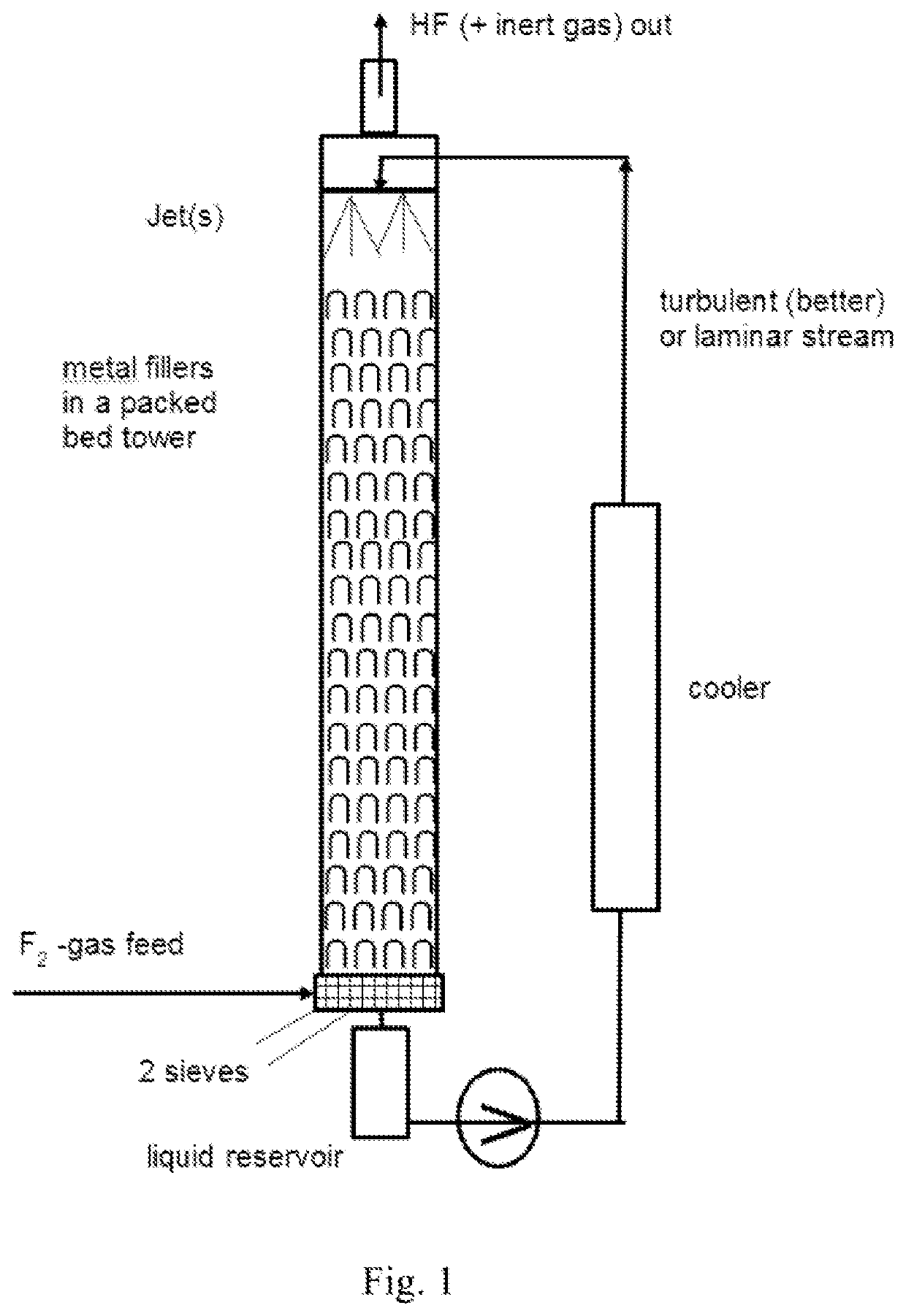
[0227]In a Batch fluorination counter-current apparatus having a pressure valve at the top which is set to 20 bar and with a total volume of 10 l (see drawing 1), 4.0 kg (97.4 mol, 5.1 l) of absolute acetonitrile were filled and the pump was started. The for the cooler a water cooling with a water temperature of 8° C. was used. When the temperature of the acetonitrile reached 15° C., the conc. F2 valve was opened with a dosage of 20 mol F2 gas / h. For this trial, the F2-gas had a concentration of 97% / h. Some purge gas leaves the apparatus toge...

example 2

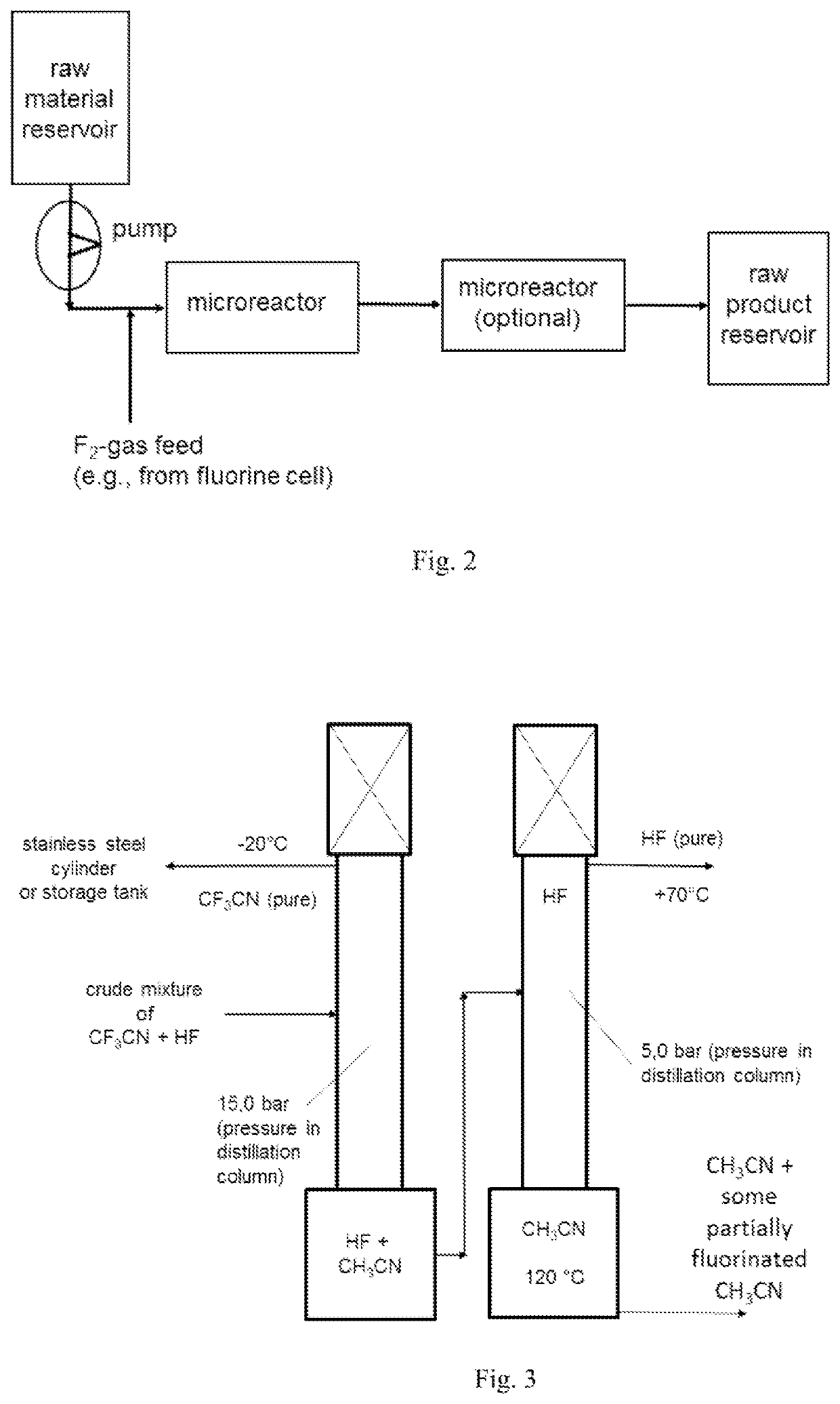
[0234]The fluorination of CH3CN was repeated continuously in a microreactor system using in lab a 27 ml SiCmicroreactor from Chemtrix. The CH3CN and F2 feed was set to a molar ratio of 1:3.1 and the reactor was kept at 5° C. The liquid feed was 234 g (5.7 mol, 300 ml) CH3CN per hour. The F2-gas stream, which come directly from a fluorine electrolysis cell (controlled with a Bronkhorst mass flow meter), was fed together with the CH3CN in a split and re-combine system before it entered into the microreactor channels. The achieved yield after continuous 2 column distillation like described in example 1 gave a CF3CN yield of 96%.

example 3

[0235]

[0236]Methane sulfonic acid fluoride was fluorinated in batch at 10° C. according to Example 1. The yield was 78% after a continuous fine distillation.

[0237]The fluorination product trifluoromethane sulfonyl fluoride (TFSAF) gives triflic acid after hydrolysis or can be used as raw material to prepare LiTFSI (Li-salt of 1,1,1-trifluoro-N-[(trifluoromethyl)sulfonyl]-methanesulfonamide).


PUM

PropertyMeasurementUnit
pressureaaaaaaaaaa
temperatureaaaaaaaaaa

Abstract

The invention relates to a use of a fluorination gas, and the elemental fluorine (F2) is present in a high concentration, for example, in a concentration of elemental fluorine (F2), especially of equal to much higher than 15 or even 20% by volume, and to a process for the manufacture of a fluorinated compound by direct fluorination employing a fluorination gas, wherein the elemental fluorine (F2) is present in a high concentration. The process of the invention is directed to the manufacture of a fluorinated compound, for the exception of fluorinated benzene, by direct fluorination. Especially the invention is of interest in the preparation of fluorinated organic compounds, final products and as well intermediates, for usage in agro-, pharma-, electronics-, catalyst, solvent and other functional chemical applications. The fluorination process of the invention may be performed batch-wise or in a continuous manner.

Description

BACKGROUND OF THE INVENTIONField of the Disclosure[0001]The invention relates to process for the manufacture or preparation of fluorinated inorganic compounds, respectively, using a fluorination gas comprising elemental fluorine (F2). The process of the invention, for example, can comprise a batch or continuous manufacture or preparation of fluorinated inorganic compounds, respectively, using fluorination gas comprising elemental fluorine (F2).Description of Related Art[0002]Fluorinated organic compounds in industrial scale are prepared by fluorine halogen exchange using anhydrous HF, addition of HF to olefinic double bonds, fluorinating agents like amine×nHF, electrofluorination with HF (in situ generation of F2) where in latter case selectivity, scalability and missing environmental friendliness (formation of very toxic partial fluorinated compounds) often is and remains an unsolved problem. Another existing fluorination procedure is using F2-gas directly. But this requires—beside...

Claims


Application Information

Patent Timeline
Patent Type & Authority Applications(United States)
IPC IPC(8): C07C253/30C01B21/083C07C67/307C07C201/12C07C303/22C07D317/42C07B39/00
CPCC07C253/30C01B21/0835C07C67/307C07B39/00C07C303/22C07D317/42C07C201/12C01C3/004C01B21/0832C07C255/10C07C309/80C07C69/63C07C205/12C07C255/50C07C17/06C07C25/13C07C311/65C07C205/11
Inventor ZHOU, CHANGYUEDU, HONGJUNWU, WENTING
Owner FUJIAN YONGJING TECH CO LTD
Why Eureka
Try Eureka