Industrial Process for Manufacturing of Perfluoropentane (PFP)

a technology of perfluoropentane and industrial process, which is applied in the field of new industrial process for manufacturing of perfluoropentane (pfp), can solve the problems of inability to use human raw materials, inability to synthesis and final purification of perfluorinated compounds to an acceptable quality in general use, and high cost of raw materials due to electric power consumption. , to achieve the effect of reducing and simplifying the number of separation steps, avoiding time and energy consumption

Pending Publication Date: 2022-08-11
FUJIAN YONGJING TECH CO LTD
View PDF0 Cites 0 Cited by
  • Summary
  • Abstract
  • Description
  • Claims
  • Application Information

AI Technical Summary

Benefits of technology

[0209]A very particular advantage of the present invention employing a microreactor, or a continuous flow reactor with the before said lateral dimensions, the number of separating steps can be reduced and simplified, and may be devoid of time and energy consuming, e.g. intermediate, distillation steps. Especially, it is a particular advantage of the present invention employing a microreactor, or a continuous flow reactor with the before said lateral dimensions, that for separating simply phase separation methods can be employed, and the non-consumed reaction components may be recycled into the process, or otherwise be used as a product itself, as applicable or desired.
[0210]In addition to the preferred embodiments of the present invention using a microreactor according to the invention, in addition or alternatively to using a microreactor, it is also possible to employ a plug flow reactor or a tubular flow reactor, respectively.
[0211]Plug flow reactor or tubular flow reactor, respectively, and their operation conditions, are well known to those skilled in the field.
[0212]Although the use of a continuous flow reactor with upper lateral dimensions of about ≤5 mm, or of about ≤4 mm, respectively, and in particular of a microreactor, is particularly preferred in the present invention, depending on the circumstances, it could be imagined that somebody dispenses with an microreactor, then of course with yield losses and higher residence time, higher temperature, and instead takes a plug flow reactor or turbulent flow reactor, respectively. However, this could have a potential advantage, taking note of the mentioned possibly disadvantageous yield losses, namely the advantage that the probability of possible blockages (tar particle formation by non-ideal driving style) could be reduced because the diameters of the tubes or channels of a plug flow reactor are greater than those of a microreactor.
[0213]The possibly allegeable disadvantage of this variant using a plug flow reactor or a tubular flow reactor, however, may also be seen only as subjective point of view, but on the other hand under certain process constraints in a region or at a production facility may still be appropriate, and loss of yields be considered of less importance or even being acceptable in view of other advantages or avoidance of constraints.
[0214]In the following, the invention is more particularly described in the context of using a microreactor. Preferentially, a microreactor used according to the invention is a ceramic continuous flow reactor, more preferably an SiC (silicon carbide) continuous flow reactor, and can be used for material production at a multi-to scale. Within integrated heat exchangers and SiC materials of construction, it gives optimal control of challenging flow chemistry application. The compact, modular construction of the flow production reactor enables, advantageously for: long term flexibility towards different process types; access to a range of production volumes (5 to 400 l / h); intensified chemical production where space is limited; unrivalled chemical compatibility and thermal control.

Problems solved by technology

Unfortunately synthesis and final purification of perfluorinated compounds to an acceptable quality for use in humans in general is very challenging, because partially fluorinated compounds are very toxic, and sometimes use in humans is even impossible due to uncomplete fluorination reaction and / or due to a too low selectivity of chemical reaction, or just due to the use of impure raw materials.
The existing main technologies for making perfluorinated compounds are either by so-called telomerization reaction (a linear dimerization of 1,3-dienes with simultaneous addition of a nucleophile in a catalytic reaction, the C—F-bond is formed already) which mostly always leads to mixtures of compounds with different chain lengths, or by electrofluorination (electrochemical fluorination, with local in situ generation of F2 at electrodes) in HF as solvent, and disadvantages such as, for example, raw material which is expensive due to electric power consumption, often low selectivity due to uncomplete fluorination and / or C—C-bond breaking.
Furthermore, on the one side, achievable yields in electrofluorination are quite low due to the needed purification, and achievable conversions are low as often organic material deposes on electrodes and thereby can cause stopping the reaction.
Besides this technical drawback of lifetime of the telomerization catalyst, achievable PFP purity in industrial scale is another drawback of this sequence.
In U.S. Pat. No. 5,093,432 (1992) some reactor types (101 scale) are disclosed but as this are just “vessels” and no “tubes”, contact time between F2-gas and the liquid with the substrate as well as heat exchange is very bad and led to very long reaction times and loss of some F2— gas especially in reactor types like shown in FIG. 1, a little bit better in FIG. 2 using a recirculating stream but all this which results in bad space / time yields and finally does not fit for industrial scale production.
All this known processes and reactor types published in that journals and patents mentioned above do not fit either regarding availability of raw material, selectivity, achievable purity for Pharma application or just scalability to economic industrial scale as no suitable reactor type is disclosed.
All these challenges lead to quite high manufacturing costs, high consumption of energy and much toxic waste formation, e.g., formation of undesired salts and / or undesired organic compounds.
As shown herein before the prior art processes are not yet optimal and have several disadvantages.

Method used


Image

  • Industrial Process for Manufacturing of Perfluoropentane (PFP)
  • Industrial Process for Manufacturing of Perfluoropentane (PFP)
  • Industrial Process for Manufacturing of Perfluoropentane (PFP)

Examples


example 1

[0233]Both steps done in an autoclave:

[0234]A 250 ml Roth autoclave with HDPTFE-inliner (made by company Berghof Fluoroplastics), magnetic stirrer, deep pipe and outlet with pressure valve over the gas phase (with an efficient scrubber after the valve) was filled with 100 g (1.0 mol) 4-methylbutyrolactone (+ / −) and put into an ice bath. 20% F2 (80% N2) was fed out of a gas cylinder over the deep pipe at room temperature into the autoclave, the pressure valve was adjusted to 5 bar while N2 and formed HF were leaving the autoclave together. The F2-dosage was done in that manner that the temperature in the autoclave did NOT exceed 40° C. After 4 h, no exothermic activity could be observed any more. Based on the 20% F2, 380 g (10.0 mol) F2 were consumed until the exothermic activity has significantly dropped down. Stirring was continued for 1 more h at 5 bar pressure. The autoclave was not degassed to make sure that HF has stayed as solvent for the next step in the solution. The pressur...

example 2

[0235]Both steps done in a Batch synthesis and in a loop reactor.

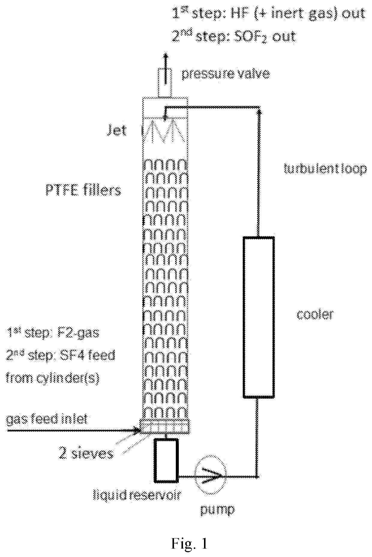
[0236]Apparatus: A column with a length of 30 cm with PTFE fillings and a diameter of 5 cm was used according to the drawing below. The liquid reservoir had a volume of 2 l. The pump was a centrifugal pump from company Schmitt. A pressure valve on top of the tower was installed to regulate the pressure, a cooling trap was installed after the pressure valve which was in use for the 2nd step only to collect some PFP leaving with the gas stream.

[0237]See FIG. 1 for apparatus and reaction.

[0238]The reservoir was filled with 1 kg (9.99 mol) 4-Methylbutyrolactone (+ / −) and the pump was started (flow ˜1500 l / h). 10% F2-gas (in N2) was fed over a Bronkhorst mass flow meter into the tower so that the reaction temperature was kept at 30° C. while the pressure on the tower was kept at 2 bar abs. by the pressure valve. After 1 h 3.04 kg (80.0 mol) F2 were fed into the system while the inert N2 together with HF left the apparatus o...

example 3

[0239]Continuous preparation of PFP in microreactor system

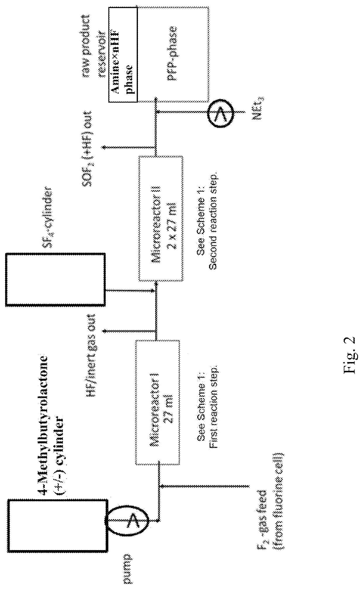
[0240]See FIG. 2 for apparatus and reaction.

[0241]One 27 ml Microreactor from Chemtrix made out of SiC was used for the 1st step, 2 in series connected 27 ml microreactors were used for 2nd step. All 3 microreactors were operated at 30° C., the pressure after 1st microreactor was adjusted to 5 bar by using a pressure valve installed at HF / inertgas outlet at the cyclone, which is not shown in the drawing. Pressure after 2nd microreactor is adjusted to 2 bar abs. by a pressure valve installed at SOF2 outlet at another cyclone, which is also not shown in the drawing. The raw material reservoir contains a double wall jacket and is cooled to 0° C. 100 g (1.0 mol) 4-methylbutyrolactone was fed together with 323 g (8.5 mol) F2 directly from a fluorine cell additional diluted with 10% N2 over a Bronkhorst mass flow meter and over 1 h into the 1st microreactor, a very strong exothermicity was observed so that a cooling machine (−20° C...


PUM

PropertyMeasurementUnit
natural abundanceaaaaaaaaaa
melting temperatureaaaaaaaaaa

Abstract

The invention relates to a new industrial process for manufacturing of perfluoropen-tane (PFP), and to the manufacture of a novel intermediate compound thereof, as well as to the novel intermediate compound itself and the use thereof in the process for manu-facturing of perfluoropentane (PFP). Accordingly, the invention relates to a process for the manufacture of the compound PFP (perfluoropentane), and/or of the compound perfluorinated 4-methylbutyrolactone, i.e., the precursor or intermediate compound of PFP (perfluoropentane), characterized in that the process comprises direct fluorination reaction with F2 gas as the fluorination agent, and/or from the fluorination reaction with SF4 as the fluorination agent. The present invention provides an efficient and simplified new industrial process for manufacturing of perfluoropentane (PFP) and/or of the compound perfluorinated 4-methylbutyrolactone, and preferably enabling large-scale and/or industrial production of perfluoropentane (PFP) and/or of the compound perfluorinated 4-methylbutyrolactone by means of special equipment and special reactor design.

Description

BACKGROUND OF THE INVENTION1. Field of the Invention[0001]The invention relates to a new industrial process for manufacturing of perfluoropentane (PFP), and to the manufacture of a novel intermediate compound thereof, as well as to the novel intermediate compound itself and the use thereof in the process for manufacturing of perfluoropentane (PFP).2. Description of the Prior Art[0002]Perfluoropentane(PFP) or dodecafluoropentane (UPAC name) is also known under its INN / USAN name as perflenapent.[0003]International nonproprietary name (INN) is an official generic and non-proprietary name given to a pharmaceutical drug or an active ingredient. United States Adopted Names (USAN) are unique nonproprietary names assigned to pharmaceuticals marketed in the United States. Each name is assigned by the USAN Council, which is co-sponsored by the American Medical Association (AMA), the United States Pharmacopeial Convention (USP), and the American Pharmacists Association (APhA).[0004]Perfluorope...

Claims


Application Information

Patent Timeline
Patent Type & Authority Applications(United States)
IPC IPC(8): C07C17/07C07D307/33C07C17/383
CPCC07C17/07C07C17/383C07D307/33A47B88/919A47B96/20A47B2220/0077C07C17/093C07C19/08
Inventor LUO, WEIFENDING, RONGWEN
Owner FUJIAN YONGJING TECH CO LTD
Why Eureka
Try Eureka