
Display panel and display device

Inactive Publication Date: 2022-05-05
SHENZHEN CHINA STAR OPTOELECTRONICS SEMICON DISPLAY TECH CO LTD
View PDF0 Cites 0 Cited by
  • Summary
  • Abstract
  • Description
  • Claims
  • Application Information

AI Technical Summary

Benefits of technology

The present text describes a display panel and device that increases the aperture ratio of pixels by removing the shared common electrode and replacing it with independent traces between adjacent pixels. This improves the display's quality and transmissivity. Additionally, the text explains how reducing the width of the transparent electrode's trunk and opaque areas can further increase the aperture ratio. Ultimately, this patent aims to provide a more efficient and effective display design for better user experience.

Problems solved by technology

However, LCDs still have an unbeatable position in the large-sized display area due to their mature technology and manufacturing process.
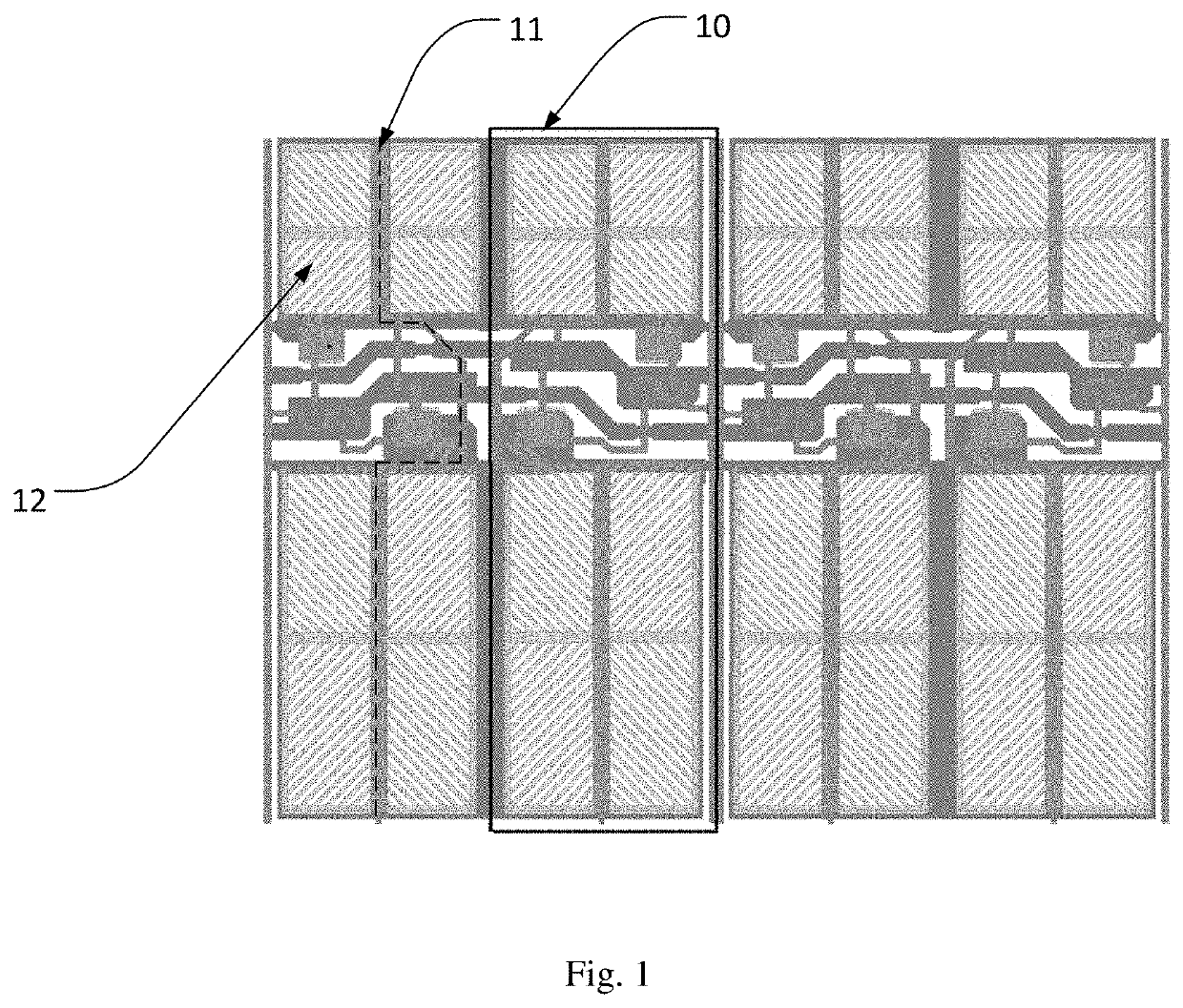
It is thus understood that the widths of the opaque areas in the display panel in the related art can not be reduced, and as a result the aperture ratio of the pixel cannot be increased.

Method used


Image

  • Display panel and display device
  • Display panel and display device

Examples


Embodiment Construction

[0022]Spatially relative terms, such as “beneath”, “below”, “lower”, “above”, “upper” and the like, may be used herein for ease of description to describe one element or feature's relationship to another element(s) or feature(s) as illustrated in the figures. It will be understood that the spatially relative terms are intended to encompass different orientations of the device in use or operation in addition to the orientation depicted in the figures.

[0023]For the purpose of description rather than limitation, the following provides such specific details as a specific system structure, interface, and technology for a thorough understanding of the application. However, it is understandable by persons skilled in the art that the application can also be implemented in other embodiments not providing such specific details. In other cases, details of a well-known apparatus, circuit and method are omitted to avoid hindering the description of the application by unnecessary details.

[0024]As...


PUM


Abstract

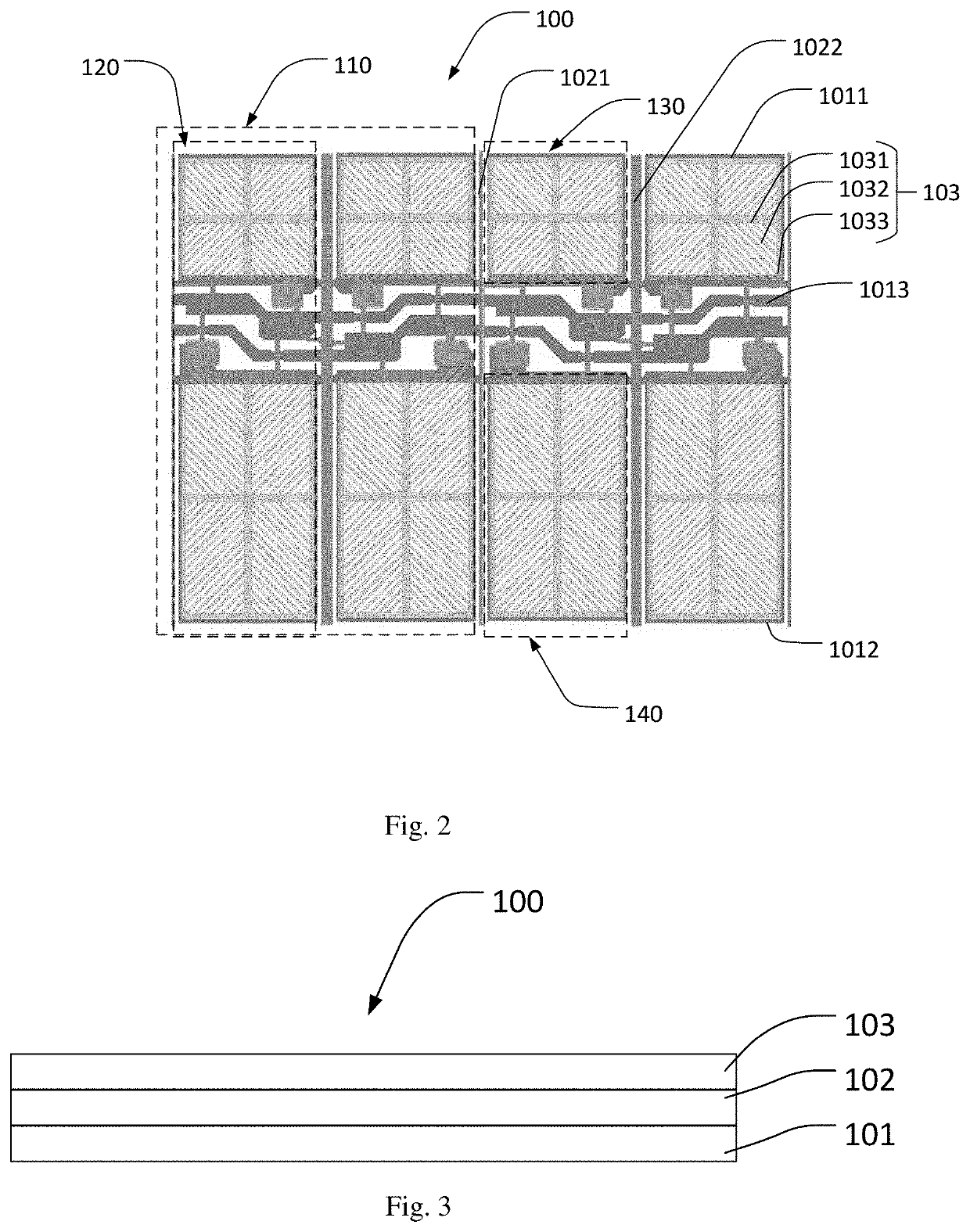
The present disclosure proposes a display panel and a display device. The display panel includes a plurality of sub-pixel groups arranged in an array, each of the sub-pixel groups having at least one sub-pixel, the sub-pixel being divided into a main area and a sub-area. The display panel also includes a first metal layer having at least one first transverse trace disposed in a spacing between the main area and the sub-area, and a second metal layer having a first longitudinal trace. The first metal layer includes a first metal trace in the main area. The first metal trace surrounds the main area. The first metal layer includes a second metal trace in the sub-area. The second metal trace surrounds the sub-area. The first longitudinal trace being disposed above the first metal layer and corresponding between adjacent sub-pixel groups.

Description

BACKGROUND1. Field of the Invention[0001]The present disclosure relates to the field of display technology, more particularly, to a display panel and a display device.2. Description of the Related Art[0002]Liquid crystal displays (LCDs), with their advantages of high brightness, long life, wide viewing angle, large size displaying, etc., have become the mainstream display technology on the current market. In recent years, with the rapid development of the semiconductor display industry, new technologies including low temperature poly-silicon (LTPS), active-matrix organic light-emitting diode (AMOLED), micro-LED, and the like, have already threatened LCDs in small and medium-sized areas. However, LCDs still have an unbeatable position in the large-sized display area due to their mature technology and manufacturing process. Therefore, reducing the cost of LCDs and increasing the transmittance of LCDs are the main tasks of LCDs in the face of many new technical challenges.[0003]As show...

Claims


Application Information

Patent Timeline
IPC IPC(8): G02F1/1343G02F1/1362
CPCG02F1/134345G02F1/134336G02F1/13439G02F1/136286G02F1/134309G02F1/1345G02F1/134318
Inventor LONG, ZHIJUAN
Owner SHENZHEN CHINA STAR OPTOELECTRONICS SEMICON DISPLAY TECH CO LTD
Learn More