Hydraulic machine comprising an improved bearing

Pending Publication Date: 2022-05-12
POCLAIN HYDRAULICS IND
View PDF0 Cites 0 Cited by
  • Summary
  • Abstract
  • Description
  • Claims
  • Application Information

AI Technical Summary

Benefits of technology

The present invention proposes a new hydraulic machine that is small but can handle heavy loads.

Problems solved by technology

Since the support surface of the rollers or the balls is limited to a contact generator, the contact pressure is very high.
But this produces bearings of large diameter, which are very bulky, expensive, and need a large-diameter shaft.
This increases the bulk of the machine and its cost, in the region of the bearing.

Method used


Image

  • Hydraulic machine comprising an improved bearing
  • Hydraulic machine comprising an improved bearing
  • Hydraulic machine comprising an improved bearing

Examples


Embodiment Construction

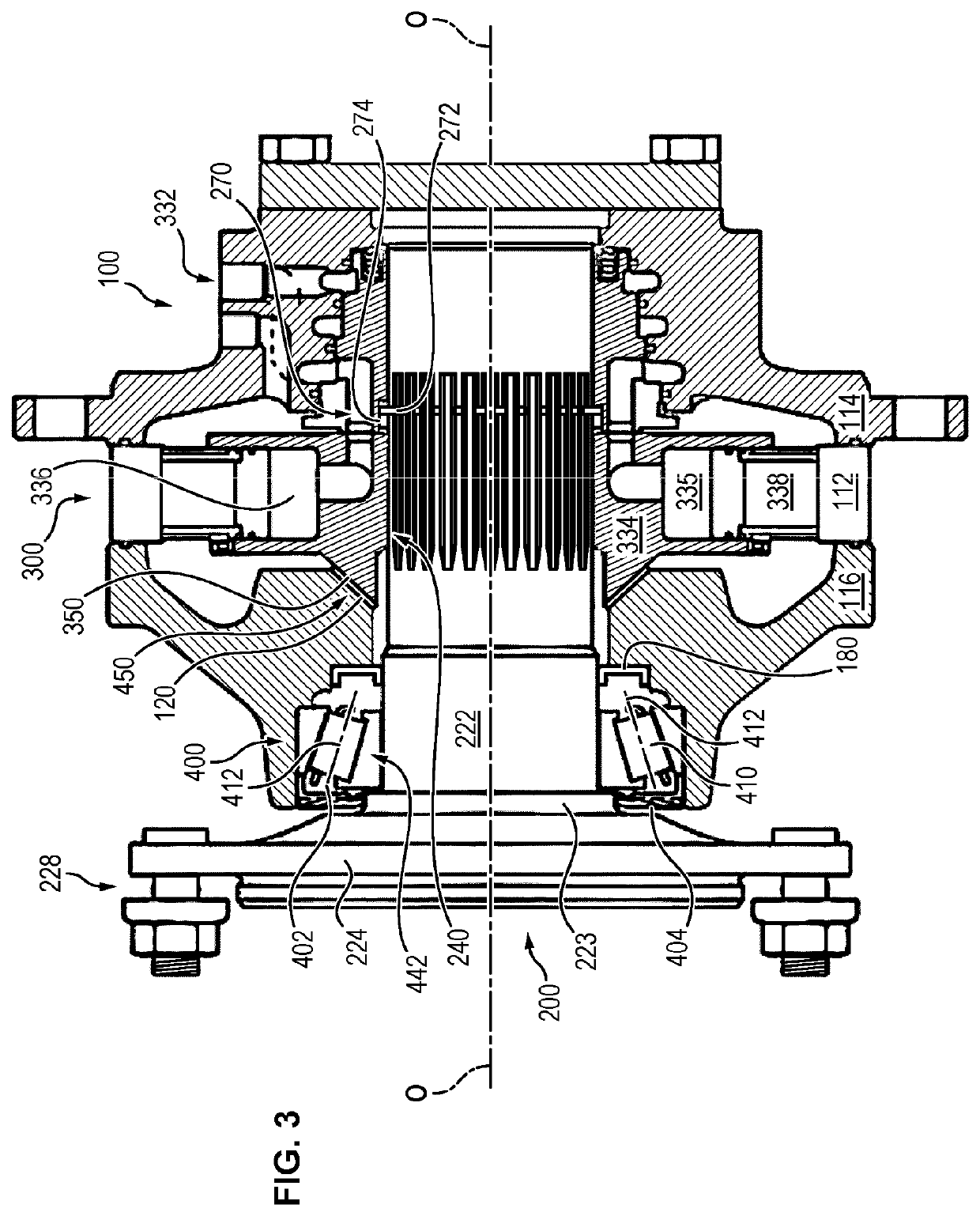
[0078]Initially the general architecture of the hydraulic machine according to the present invention illustrated in the attached FIG. 3 will now be described.

[0079]FIG. 3 shows a hydraulic machine mainly comprising four assemblies: a housing 100, a shaft 200, an assembly 300 forming a motor or pump and means 400 forming rotating guide bearings of the shaft 200 relative to the housing 100.

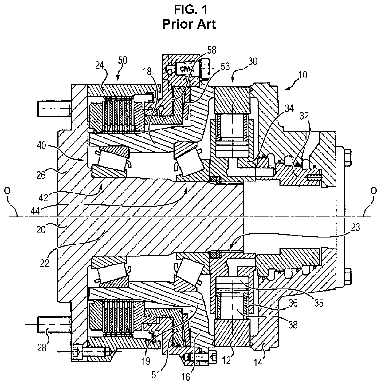
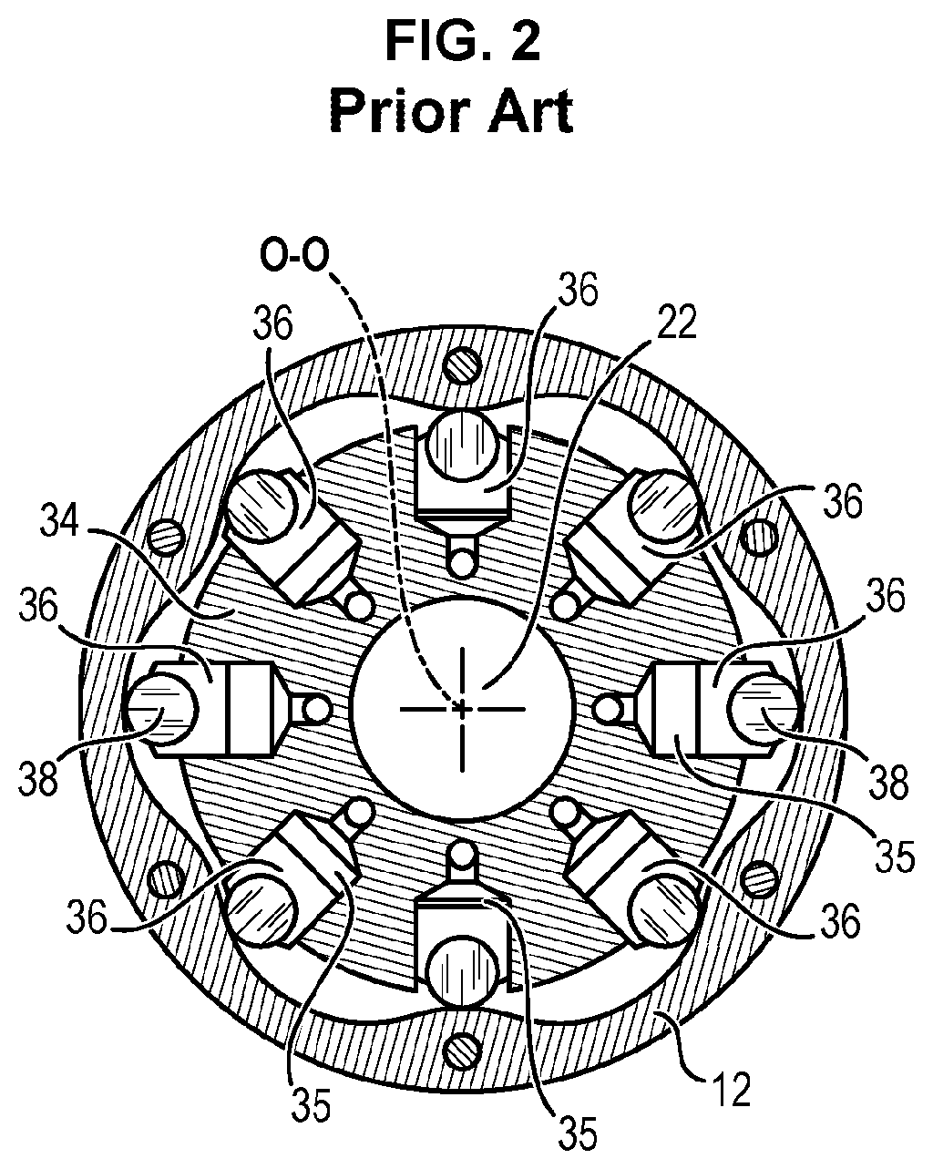
[0080]Where appropriate, the machine according to the present invention can also be fitted with a brake placed between an element of the housing 100 and an element of the shaft 200, for example a disc brake of the type illustrated in FIG. 1.

[0081]Each of these assemblies can itself form the subject of many embodiments. They will therefore not be described in detail hereinbelow.

[0082]The general structure and the general function of each of these assemblies will be simply recalled.

[0083]The housing 100 is intended to be fixed to the chassis of a machine or a vehicle. It mainly comprises a multilobed ...


PUM


Abstract

A hydraulic piston machine including a housing, a shaft that is able to rotate relative to the housing, and a cam secured to one of the housing or the shaft. A cylinder block includes pistons that are able to move in the cylinder block opposite the cam in order to generate relative rotation between the cylinder block and the cam. The cylinder block is linked in rotation to the other of the shaft or the housing. A mechanism forms rotation guide bearings for guiding the rotation of the shaft relative to the housing, which mechanism includes a tapered plain bushing interposed between a housing element and an element linked in rotation with the shaft and in which the tapered plain bushing includes a radial through-slit extending through the entire radial dimension of the bushing.

Description

TECHNICAL FIELD[0001]The present invention relates to the field of hydraulic machines. The present invention relates in particular, but not exclusively, to hydraulic machines with radial pistons.PRIOR ART[0002]Many types of hydraulic machines have already been proposed.[0003]An embodiment of a machine according to the prior art, such as illustrated in the attached FIGS. 1 and 2, is disclosed in document FR 2 796 886.[0004]The attached FIGS. 1 and 2 illustrate a hydraulic machine which essentially comprises five additional assemblies: a housing 10, a shaft 20, an assembly 30 forming motor or pump arranged between the housing 10 and the shaft 20, means 40 forming guide bearings rotating relative of the shaft 20 relative to the housing 10, around the axis O-O, and a brake 50. The housing 10 is intended to be fixed to the chassis of a machine or a vehicle.[0005]Each of the above five assemblies can form the object of many variant embodiments.[0006]According to the embodiment shown in FI...

Claims


Application Information

Patent Timeline
IPC IPC(8): F04B1/047F16C17/10
CPCF04B1/047F16C2360/42F16C17/10F16C33/046F16C33/1065F16C2360/00F04B1/0404F16C2350/00F03C1/047F03C1/0403
Inventor ENGRAND, JULIEN RENEGRILLON, GILLESQUERTELET, STEPHANE BERNARD
Owner POCLAIN HYDRAULICS IND
Why Eureka
Try Eureka