

Lifting table with height adjustment device
- Summary
- Abstract
- Description
- Claims
- Application Information
AI Technical Summary
Benefits of technology
Problems solved by technology
Method used
Image

Examples
first embodiment
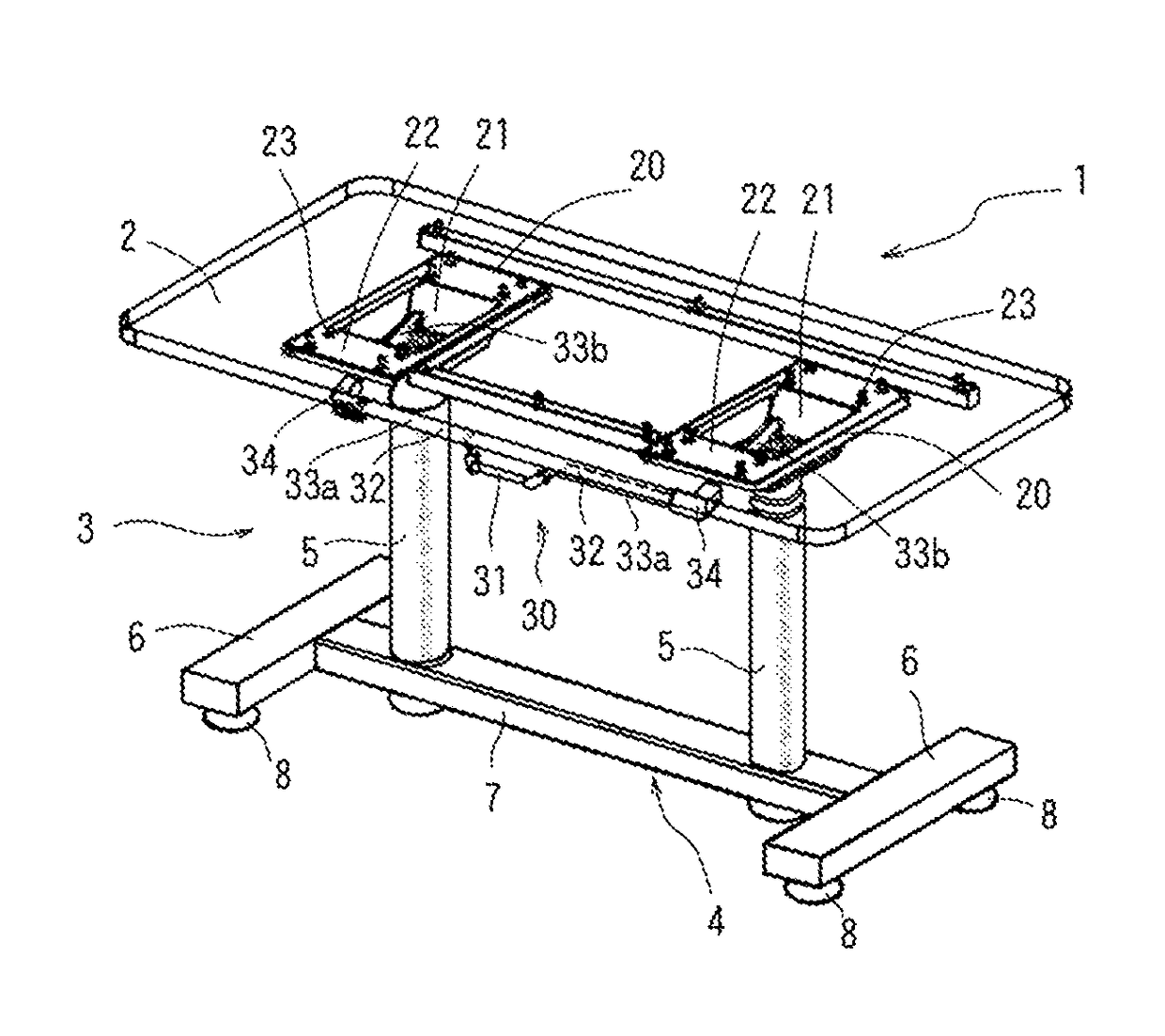
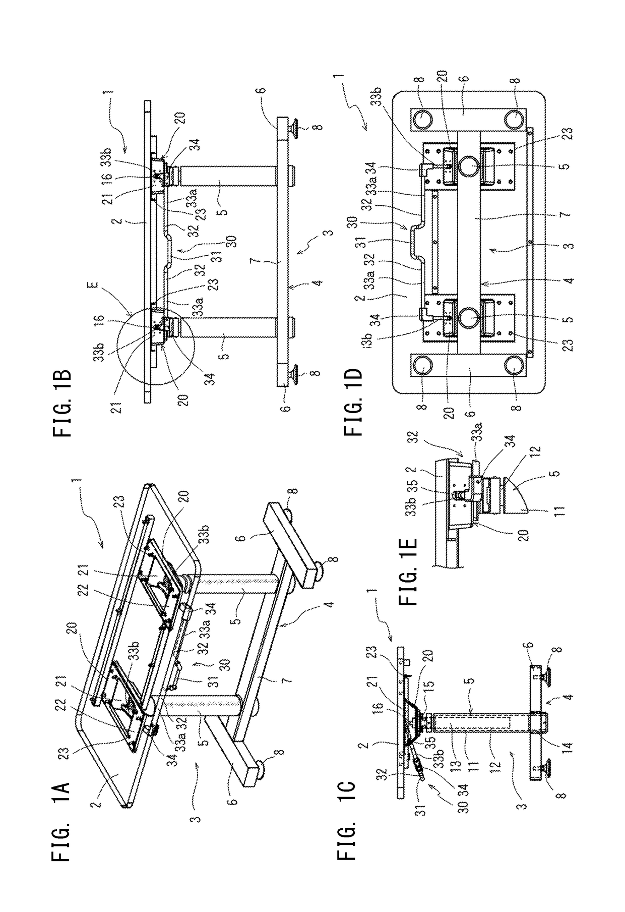
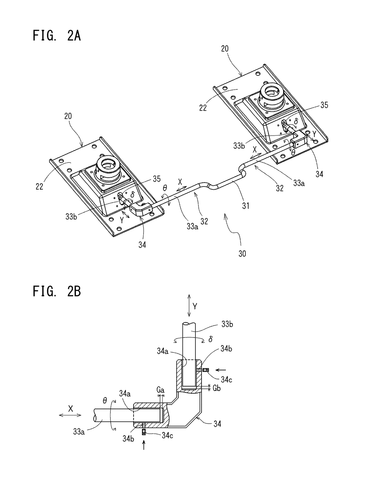
[0043]Referring now to the embodiments of the invention shown in the attached drawings, FIG. 1 shows a lifting table with height adjustment device according to the present invention, and FIG. 2 shows the details of the operation lever of the height adjustment device mounted on the lifting table shown in FIG. 1.
[0044]The first embodiment of a lifting table with the height adjustment device (hereinafter referred to as “lifting table”) is shown in FIG. 1; FIG. 1A is a perspective view of the lifting table, FIG. 1B is a front view of the lifting table, FIG. 1C is a side view of the lifting table, FIG. 1D is a top view of the lifting table and FIG. 1E is an enlarged view of the part encircled with circle E in FIG. 1B. The lifting table 1 comprises the top plate 2 and the table leg structure 3 supporting the top plate 2. The top plate 2 in the first embodiment is made of transparent glass, those in other embodiments are same, so that the table leg structure 3 can be seen through the top p...
sixth embodiment
[0063]With respect to the lifting table 1e of the sixth embodiment, the operation lever 30e is not of swinging type operated to swing in a manner of approaching the back surface of the top plate 2e but of sliding type operated to move along the back surface of the top plate 2e as shown in FIG. 7A and FIG. 7B. In other words, the operation lever 30e is composed of the first rod sections 33a, 33a extended from the left and the right of the handle 31, as two operation rod units 32, 32, and the L-shaped connectors 34, 34 which are connected to the tip ends of the handle 31. The second rod sections 33b, 33b are connected to the connectors 34, 34 along the direction orthogonal to the first rod sections 33a, 33a (the direction parallel to the top plate 2e). The second rod sections 33b, 33b bends upwards directly to approach the top plate 2e, bends again to get parallel to the top plate 2e and extends into corresponding receiving structures 20, 20 under the guidance of the guiding devices 3...
fifth embodiment
[0064]The second rod sections 33b, 33b and the third rod section 33e have air spring operation portions 36e with tapered surfaces 36t formed at the tip ends respectively in the corresponding receiving structure 20. The handle 31 of the operation lever 30e is hold, and is pushed in the direction along the back surface of the top plate 2e, the second rod sections 33b, 33b and the third rod section 33e will be guided by the guiding device 35e respectively, the air spring operation portions 36e at the tip end will push the push valves 16 of the air springs 13 with its tapered surface 36t, and operate synchronously. The connectors 34, 34 operate with same function as those of the connectors in the fifth embodiment so that the detailed description will not be repeated.
[0065]FIG. 8 is the schematic view of the seventh embodiment of the lifting table with height adjustment device according to this Invention. FIG. 8A is the front view of the lifting table, FIG. 8B is the side view of the lif...
PUM
 Abstract
Description
Claims
Application Information