
Pilot fuel injection adaptation

A technology for igniting fuel and fuel injectors, which is applied in the directions of fuel injection control, combustion engine, internal combustion piston engine, etc., can solve problems such as difficulty in determining the error of the transfer function of the fuel injector, and difficulty in accurately updating the transfer function of the fuel injector, etc. Achieve improved engine emissions and combustion stability, improved conditioning, reduced emissions and noise

Active Publication Date: 2016-12-28
FORD GLOBAL TECH LLC
View PDF4 Cites 0 Cited by
  • Summary
  • Abstract
  • Description
  • Claims
  • Application Information

AI Technical Summary

Problems solved by technology

However, when the engine is operated with short duration pilot fuel injections, it can be difficult to determine the fuel injector transfer function error
Therefore, when the engine is operated using short duration pilot fuel injections, it may be difficult to accurately update the fuel injector transfer function

Method used


Image

  • Pilot fuel injection adaptation
  • Pilot fuel injection adaptation
  • Pilot fuel injection adaptation

Examples


Embodiment Construction

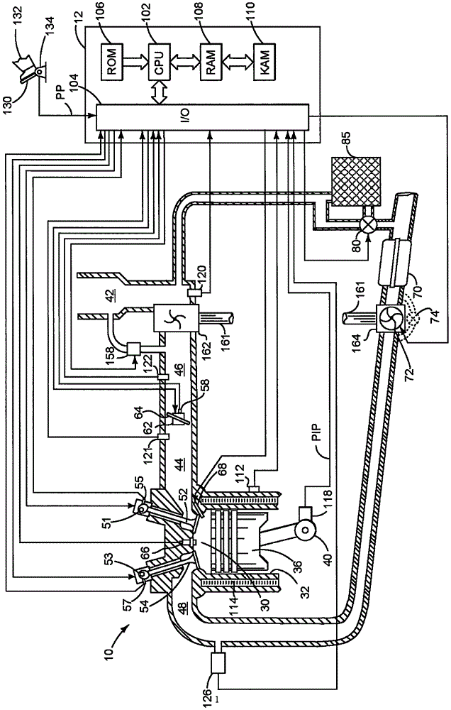
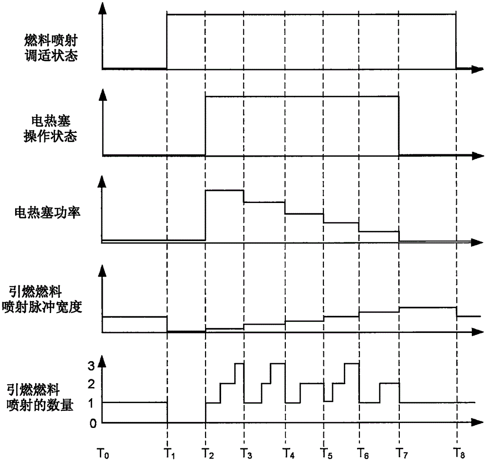
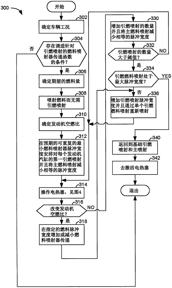
[0011] The present description relates to tuning fuel injector transfer functions to reduce engine noise and improve combustion within engine cylinders. figure 1 An example of a boosted diesel engine is shown, where image 3 and Figure 4 A method can adjust glow plug operation and combustion phasing to improve engine torque production, combustion stability, and reduce engine combustion noise. The engine operating sequence is figure 2 is shown in , where the fuel injector transfer function is tuned. image 3 and Figure 4 An example method for adjusting a transfer function describing fuel injector operation is shown.

[0012] refer to figure 1 , an internal combustion engine 10 comprising a plurality of cylinders is controlled by an electronic engine controller 12, figure 1 One cylinder of the plurality of cylinders is shown. Engine 10 includes combustion chamber 30 and cylinder walls 32 with piston 36 seated therein and connected to crankshaft 40 . Combustion chamber...


PUM


Abstract

The invention relates to pilot fuel injection adaptation. Methods and systems for adapting pilot fuel injection pulse widths are disclosed. In one example, pilot fuel injection values are varied to determine adjustments to a fuel injector transfer function and a glow plug is activated in response to a request to adapt the fuel injector transfer function so that adaptation may be improved.

Description

technical field [0001] This application relates to pilot fuel injection adaptation. Background technique [0002] Fuel may be supplied to cylinders of a diesel engine during an engine cycle by one or more fuel injection pulses. The first group of fuel injections provided to engine cylinders during a cycle of the cylinders may be referred to as pilot fuel injections. The pilot fuel injection may be followed by the main injection. Main injection may be followed by post injection during the same cylinder cycle. Pilot fuel injection may be useful to reduce engine noise, while main fuel injection has the purpose of generating engine torque. Post fuel injection may be provided to the engine to deliver thermal energy to emission control devices in the engine's exhaust system, or to provide reductant to emission control devices. Variations in fuel flow for different fuel injectors of the same type may be apparent at smaller fuel pulse widths at which the fuel injector provides p...

Claims


Application Information

Patent Timeline
IPC IPC(8): F02D41/40
CPCF02D41/403F02P19/021F02P19/026Y02T10/40F02D41/26
Inventor K·波尔坎普
Owner FORD GLOBAL TECH LLC
Learn More