
Illumination system and projection device

a projection device and projection device technology, applied in the direction of projectors, instruments, color television details, etc., can solve the problems of poor accuracy, assembly difficulty, and difficulty in size reduction, and achieve the effect of reducing the number of optical elements

Active Publication Date: 2022-06-02
CORETRONIC
View PDF4 Cites 0 Cited by
  • Summary
  • Abstract
  • Description
  • Claims
  • Application Information

AI Technical Summary

Benefits of technology

The patent text describes a new illumination system and projection device that reduces the number of optical elements, making it easier to assemble, improve accuracy, and reduce size. The system uses a special light guide and filtering module to convert the optical wavelength of the light, resulting in a more efficient and cost-effective system.

Problems solved by technology

As too many optical components are included in the illumination system, this leads to difficulty in assembly, poor accuracy, and difficulty in size reduction.

Method used


Image

  • Illumination system and projection device
  • Illumination system and projection device
  • Illumination system and projection device

Examples


Embodiment Construction

[0017]In the following detailed description of the preferred embodiments, reference is made to the accompanying drawings which form a part hereof, and in which are shown by way of illustration specific embodiments in which the disclosure may be practiced. In this regard, directional terminology, such as “top”, “bottom”, “front”, “back” etc., is used with reference to the orientation of the figure(s) being described. The components of the disclosure can be positioned in a number of different orientations. As such, the directional terminology is used for purposes of illustration and is in no way limiting.

[0018]On the other hand, the drawings are only schematic and the size of the components may be exaggerated for clarity. It is to be understood that other embodiments may be utilized and structural changes may be made without departing from the scope of the disclosure. Also, it is to be understood that the phraseology and terminology used herein are for the purpose of description and s...


PUM


Abstract

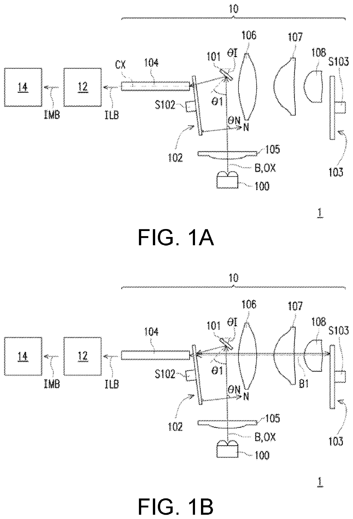
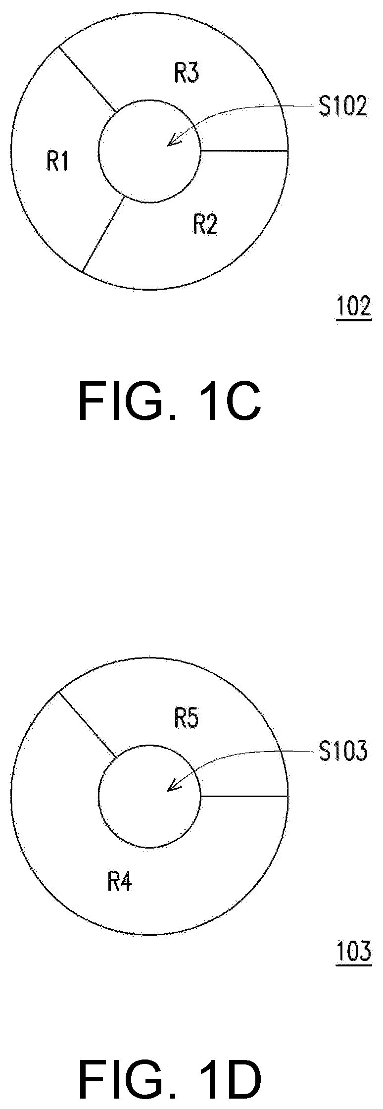
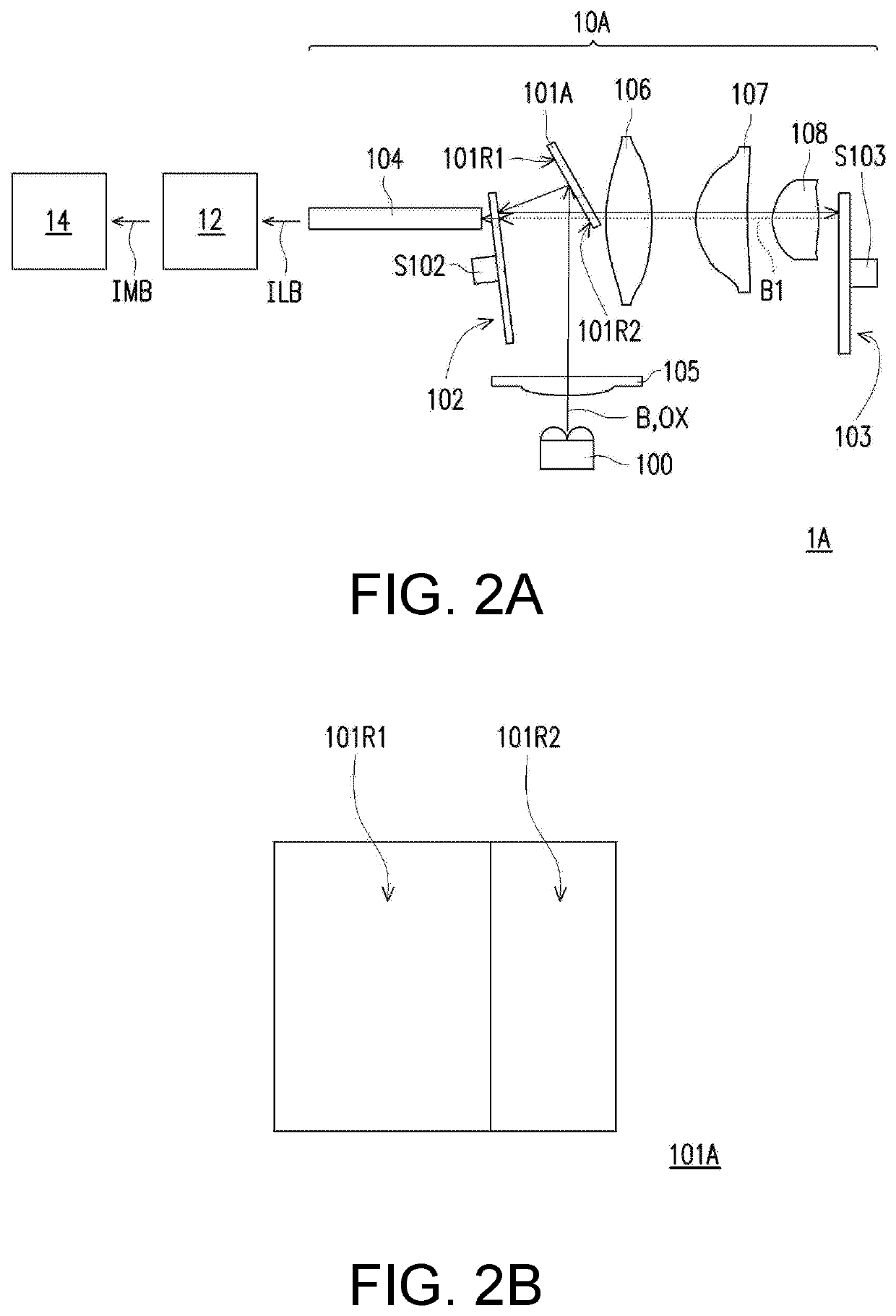
An illumination system and a projection apparatus are provided. The illumination system includes an excitation light source, a light guiding element, a filter module, an optical wavelength conversion module, and a homogenizing element. The light guiding element reflects an excitation beam coming from the excitation light source. The filter module includes a filtering region and receives the excitation beam reflected by the light guiding element. The optical wavelength conversion module includes a wavelength conversion region, receives the excitation beam reflected by the filtering region and reflects a conversion beam converted from the excitation beam. The conversion beam forms at least one color beam after passing through the filtering region of the filter module. The homogenizing element receives the excitation beam coming from the filter module and the at least one color beam. An incident angle of the excitation beam on the light guiding element is θ1, and θ1>0°.

Description

CROSS-REFERENCE TO RELATED APPLICATION[0001]This application claims the priority benefit of China application serial no. 202011353154.0, filed on Nov. 27, 2020. The entirety of the above-mentioned patent application is hereby incorporated by reference herein and made a part of this specification.BACKGROUNDTechnical Field[0002]This disclosure relates to an optical apparatus and an optical system, and in particular to a projection apparatus and an illumination system.Description of Related Art[0003]In a conventional projection apparatus, an excitation beam is first transmitted to an optical wavelength conversion module through a beam splitting element, multiple lenses, and multiple mirrors, and then the optical wavelength conversion module converts the excitation beam into a conversion beam, and the conversion beam is then transmitted back through the beam splitting element and other lenses to a filter module. As too many optical components are included in the illumination system, thi...

Claims


Application Information

Patent Timeline
Patent Type & Authority Applications(United States)
IPC IPC(8): G03B33/08G03B21/20
CPCG03B33/08G03B21/204G03B21/208G03B21/2066G02B26/008G02B5/26H04N9/3152H04N9/3161H04N9/3158G03B21/2033G03B21/2073
Inventor HSIEH, WAN-TINGFAN, CHEN-WEI
Owner CORETRONIC
Learn More