Active pedestrian hood hinge with integrated latch assembly
a technology of latch assembly and active hinge, which is applied in the direction of wing accessories, pedestrian/occupant safety arrangements, vehicular safety arrangements, etc., can solve the problem of limiting the available crush space, and achieve the effect of increasing safety and increasing safety
- Summary
- Abstract
- Description
- Claims
- Application Information
AI Technical Summary
Benefits of technology
Problems solved by technology
Method used
Image


Examples
first embodiment
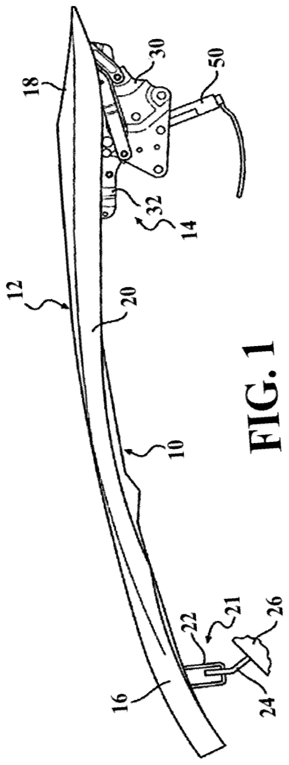
[0083]FIGS. 3-9 present an active hinge 14 according to another aspect of the disclosure. FIG. 3 presents the active hinge 14 in its non-deployed condition. The active hinge 14 generally includes a body bracket 30, a hood bracket 32, a deploy bracket 34, and a pivot linkage mechanism interconnecting the body bracket 30 and deploy bracket 34. As best shown in FIG. 4, the pivot linkage mechanism includes a first link 36 and a second link 38 arranged to define a four-bar linkage 40. The first link 36 has one end pivotally connected to the body bracket 30 via a first pivot pin 60 and its opposite end pivotally connected to deploy bracket 34 via a second pivot pin 62. Similarly, second link 38 is shown having a first end pivotally connected to body bracket 30 via a first pivot pin 64 and its second end pivotally connected to deploy bracket 34 via a second pivot pin 66. A third pivot pin 70 pivotally connects a terminal end segment of deploy bracket 34 to the hood bracket 32.
[0084]With re...
second embodiment
[0097]It should be appreciated that the pawl 80, 80′ and safety bolt 88, 88′ may alternatively be placed on another of the body bracket, 30, hood bracket 32, deploy bracket 34 or links 36, 38 without departing from the scope of the subject disclosure. It should also be appreciated that an active hinge 14′ may be assembled in accordance with the method presented in FIG. 11.
third embodiment
[0098]FIGS. 19-20 present a pawl 80A according to an aspect of the disclosure. According to this embodiment, the lower pocket 86A of the hook portion 84A of the pawl 80A is extended such that it surrounds more than half of the outer circumference of the safety bolt 88 to provide increased locking security while the pawl 80A is positioned in the locked position. As shown, a first distance L1 between the pivot fifth pin 82 and the engagement face 85 is more than twice that of a second distance L2 between the fifth pin 82 and the contact face 98. This provides a further reduced actuator stroke length for moving the pawl 80A from the locked to unlocked position.
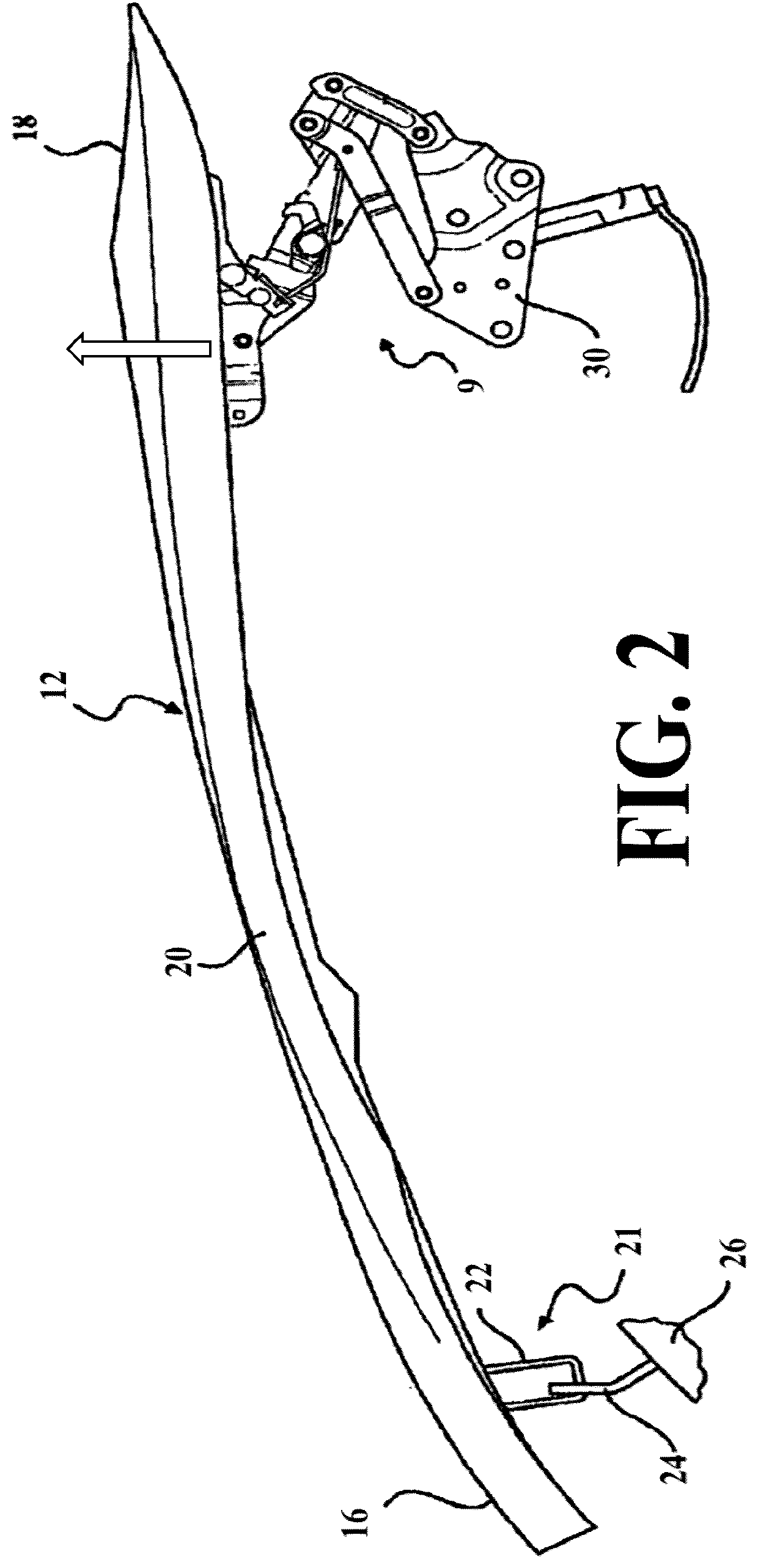
[0099]Now referring to FIG. 21A and FIG. 21B, in addition to FIGS. 1 through 20, an active hinge 9 is provided and includes a hood bracket 32 for attachment to a vehicle hood 12, a body bracket 30 for attachment to a vehicle body, and may include a number of intermediary components such as bracket 34 and linkages 36, 38, for exam...
PUM
 Abstract
Description
Claims
Application Information
 - R&D
- Intellectual Property
- Life Sciences
- Materials
- Tech Scout
- Unparalleled Data Quality
- Higher Quality Content
- 60% Fewer Hallucinations
Browse by: Latest US Patents, China's latest patents, Technical Efficacy Thesaurus, Application Domain, Technology Topic, Popular Technical Reports.
© 2025 PatSnap. All rights reserved.Legal|Privacy policy|Modern Slavery Act Transparency Statement|Sitemap|About US| Contact US: help@patsnap.com