

Remote operation of a powered burden rail car
- Summary
- Abstract
- Description
- Claims
- Application Information
AI Technical Summary
Benefits of technology
Problems solved by technology
Method used
Image

Examples
Example
DETAILED DESCRIPTION OF THE DRAWINGS
[0086]In this disclosure, an apparatus and a method are described that relates to a heavy, multi-axle, self-propelled freight rail car and it relates more particularly to a method of positioning a traction motor in a standard two axle truck assembly.
PRIOR ART
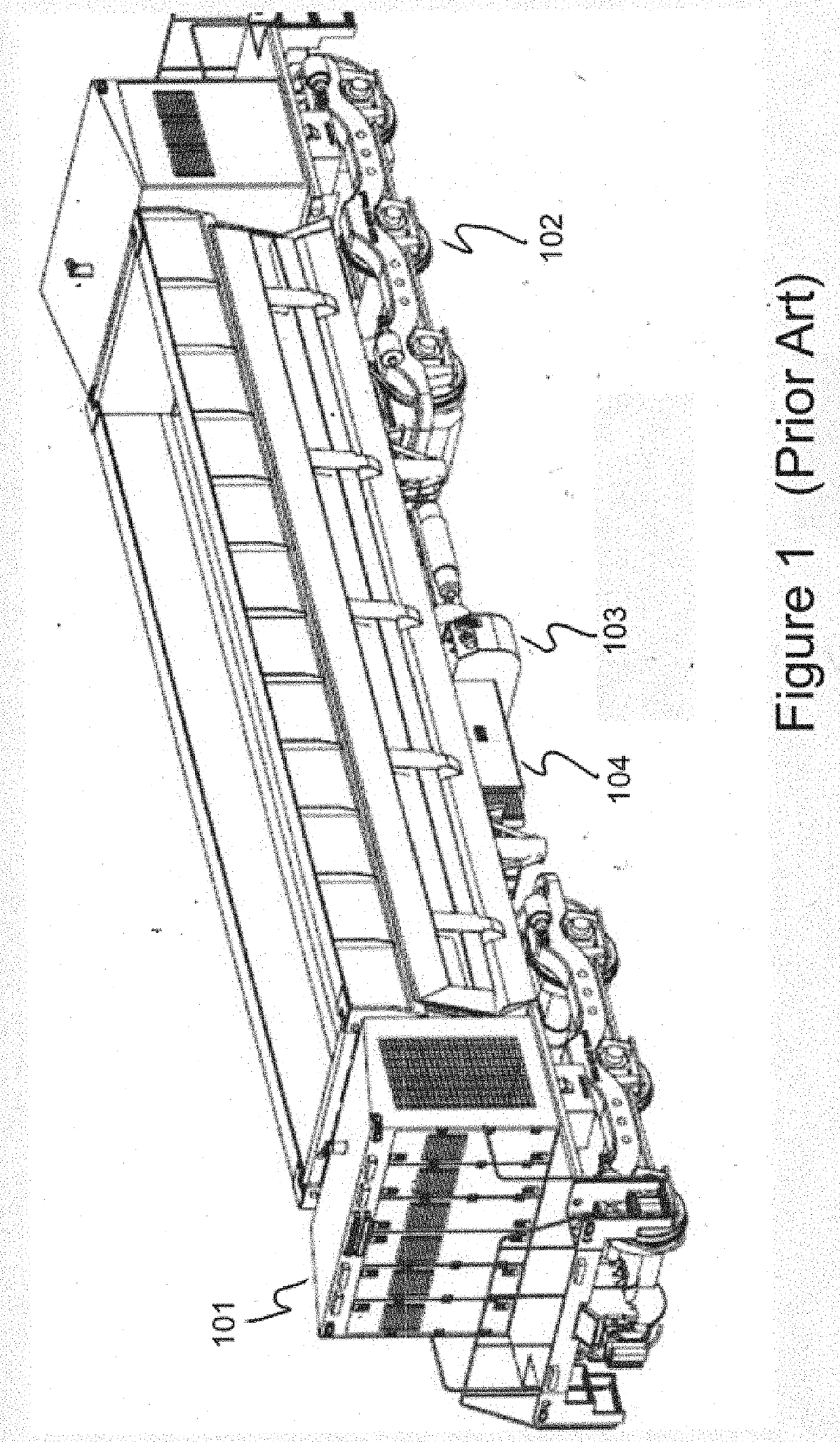
[0087]FIG. 1 is an isometric view of a prior art self-powered burden car using 3 axle locomotive trucks 102 of U.S. Pat. No. 8,428,796. The burden car includes, gensets 101 and genset access platform at opposing ends of the car, a sensor array, battery box 104, fuel tank 103 and electrical cabinet. One or more of the truck assemblies comprises two traction motors powered by the electrical energy produced by the genset.
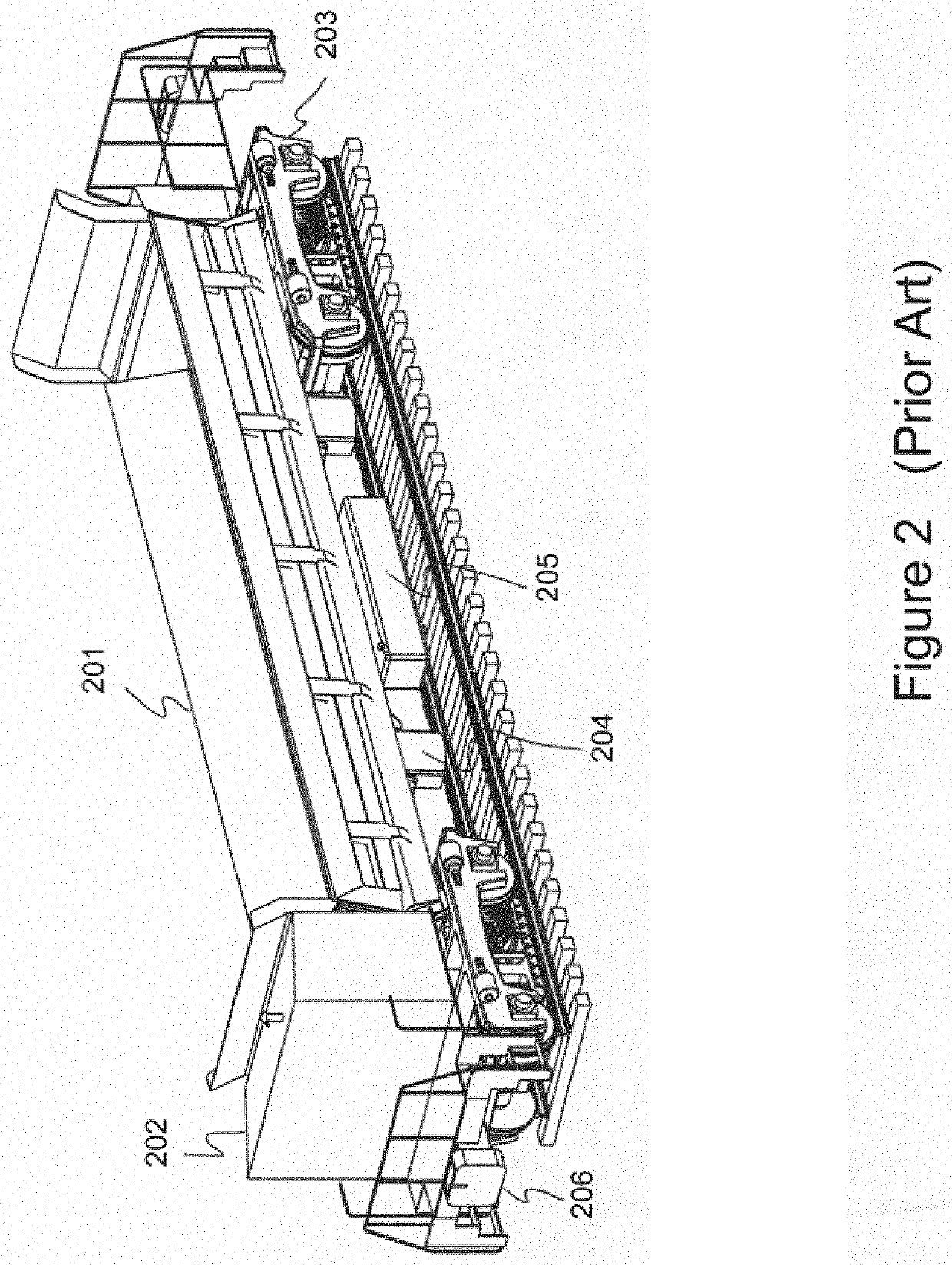
[0088]FIG. 2 is an isometric schematic view of an automated self-powered side dumping car according to the prior art. A cargo box 201 is attached to a frame which, in turn, is mounted on two truck assemblies 203. The cargo box 201 can be tilted for unloading by hydraulic or pneum...
PUM
 Abstract
Description
Claims
Application Information