Unlock instant, AI-driven research and patent intelligence for your innovation.

Image processing apparatus and non-transitory computer readable medium

a technology of image processing and computer readable media, which is applied in the direction of electrical equipment,pictoral communication, etc., can solve the problems of separating one value into two values, affecting the visibility of images, so as to achieve the effect of improving the visibility of images

Active Publication Date: 2022-06-23
FUJIFILM BUSINESS INNOVATION CORP
View PDF0 Cites 0 Cited by
  • Summary
  • Abstract
  • Description
  • Claims
  • Application Information

AI Technical Summary

Benefits of technology

This approach enhances image visibility by setting optimal reproduction parameters considering the color gamut of the output device, improving dark area visibility and overall image quality.

Problems solved by technology

Furthermore, the dimensional ratios in the drawings are exaggerated for the sake of convenience and may sometimes differ from the actual ratios.
As it is clear from Expression 2, separating one value into two values is normally called an ill-posed problem.
In an ill-posed problem, the illumination component or the reflectance component is not determinable unless the other component is estimated using some type of method.
In FIG. 5, the trees and the windows in the building are dark areas with poor visibility.
In FIG. 6, the trees and the building are dark areas with poor visibility.
Although the brightness of the trees is the same between FIGS. 5 and 6, the brightness of the building is lower in FIG. 6, resulting in the overall image in FIG. 6 having poorer visibility.
As mentioned in the above example, if dark areas have the same brightness, the larger dark area has poorer visibility.
Therefore, when a reproduction parameter is calculated using the color gamut of the input device, the reproduction parameter is larger than a reproduction parameter calculated using the smaller color gamut of the output device, and is too intense in the output-device space.

Method used


Image

  • Image processing apparatus and non-transitory computer readable medium
  • Image processing apparatus and non-transitory computer readable medium
  • Image processing apparatus and non-transitory computer readable medium

Examples


first exemplary embodiment

[0031]A first exemplary embodiment of the present disclosure will be described below with reference to the drawings. In the drawings, identical or equivalent components and sections are given the same reference signs. Furthermore, the dimensional ratios in the drawings are exaggerated for the sake of convenience and may sometimes differ from the actual ratios.

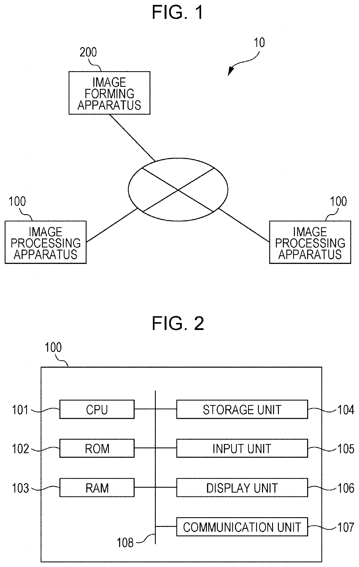
[0032]FIG. 1 schematically illustrates the configuration of an image processing system 10 according to the first exemplary embodiment.

[0033]As shown in FIG. 1, in the image processing system 10, image processing apparatuses 100 and an image forming apparatus 200 are connected to a communication unit, such as a network. As will be described later, the communication unit used may be any of various types of networks, such as the Internet, an intranet, and Ethernet (registered trademark). Although two image processing apparatuses 100 and a single image forming apparatus 200 are shown in FIG. 1, the number of image processing appara...

second exemplary embodiment

[0091]Next, a second exemplary embodiment will be described.

[0092]The first exemplary embodiment described above relates to an example where a reproduction parameter is estimated by using the average brightness of a dark area alone (see Expression 8). In the second exemplary embodiment, a reproduction parameter is estimated in view of the percentage of the size (i.e., the number of pixels) of a dark area.

[0093]The following description focuses on differences from the first exemplary embodiment described above, and redundant explanations will be simplified or omitted.

[0094]In order to take into account the percentage of the number of pixels in a dark area, the coefficient a in Expression 8 described in the first exemplary embodiment is replaced with a coefficient a(r) serving as a function of the percentage of the number of pixels in the dark area, as indicated in Expression 10.

α=a(r)×*ave   Expression 10

[0095]For example, assuming that the coefficient a(r) in Expression 10 is a line...

third exemplary embodiment

[0104]Next, a third exemplary embodiment will be described.

[0105]In the first exemplary embodiment and the second exemplary embodiment described above, the compression rate of the color gamut of the output device relative to that of the input device is saved in advance as information, and the calculation is performed uniformly by using the compression rate. Thus, the compression rate varies depending on the device, but does not vary depending on the image. In the third exemplary embodiment, the compression rate is calculated based on pixel information of an input image, so that the compression rate varies depending on the image. Accordingly, an output-device optimal reproduction parameter may be set more appropriately in accordance with the image.

[0106]The following description focuses on differences from the first exemplary embodiment and the second exemplary embodiment described above, and redundant explanations will be simplified or omitted.

[0107]FIG. 16 illustrates a block diagr...


PUM


Abstract

An image processing apparatus includes a processor configured to adjust a reproduction parameter for correcting image visibility by changing a degree by which the reproduction parameter is to be changed from a reference value in accordance with a ratio of a second color gamut to a first color gamut. The first color gamut indicates a range in which an image is expressible by a first device. The second color gamut indicates a range in which an image is expressible by a second device.

Description

CROSS-REFERENCE TO RELATED APPLICATIONS[0001]This application is based on and claims priority under 35 USC 119 from Japanese Patent Application No. 2020-210536 filed Dec. 18, 2020.BACKGROUND(i) Technical Field[0002]The present disclosure relates to image processing apparatuses and non-transitory computer readable media.(ii) Related Art[0003]Japanese Unexamined Patent Application Publication No. 2008-271316 discloses an image processing method including a step of calculating an average value of pixel values within an image, a step of calculating a maximum value of the pixel values within the image, a step of calculating a minimum value of the pixel values within the image, and a replacing step. In the replacing step, pixels having pixel values in a range between a value obtained by subtracting the average value from the maximum value and the minimum value have their pixel values within the image replaced by using a gradation conversion characteristic in which the brightness increases...

Claims


Application Information

Patent Timeline
Patent Type & Authority Applications(United States)
IPC IPC(8): H04N1/60H04N1/00
CPCH04N1/6066H04N2201/0094H04N1/00129H04N1/6052
Inventor NARUMI, SHOTASASAKI, MAKOTO
Owner FUJIFILM BUSINESS INNOVATION CORP