Syringe plunger finger ring structures
a technology of plunger finger and syringe, which is applied in the direction of medical devices, intravenous devices, medical devices, etc., can solve the problems of difficult operation, difficult control of syringe content, and limited surface area of plunger finger ring
- Summary
- Abstract
- Description
- Claims
- Application Information
AI Technical Summary
Benefits of technology
Problems solved by technology
Method used
Image
Examples
embodiment 76
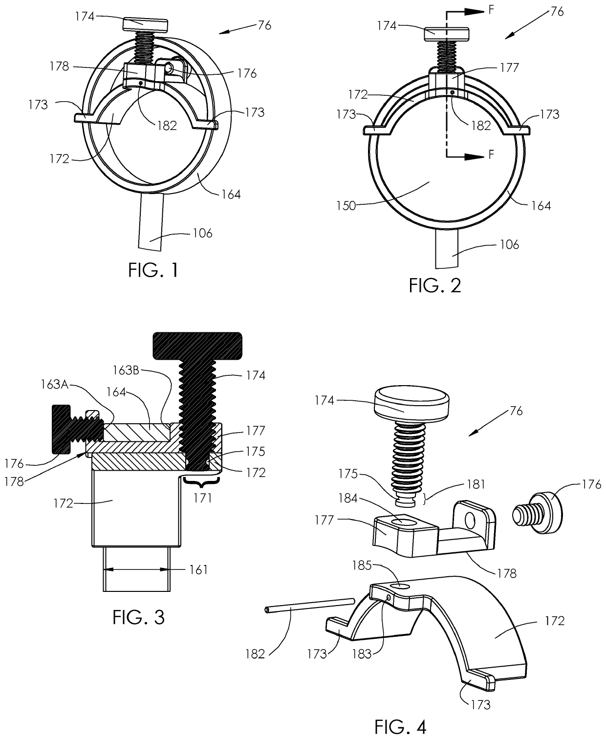
[0015]An embodiment 76 is shown in FIGS. 1-4, that includes a screw 174 adjustment of an insertable inner curved member 172 relative to an threaded holding block 178 retained within the annular member 164 open area 150 by a holding block retaining screw 176, that holding block 164 engages a lateral edge 163A of the annular member 164 connected to plunger shaft 106, and the opposing edge 1636 by screw 174 threaded shoulder 177. The lateral movement (in the direction of width 161, FIG. 3) is limited by radially outward extending ‘ears’ attached to one side of curved member 172 to allow insertion of the assembly of the holding block 178, screw 174, and curved member 172 into the open area 150 of the annular member 164. As shown in FIG. 3 cross-section F of FIG. 2, and exploded view of FIG. 4, the screw end 181 received into lateral extension 171 opening 185, having an circumferential recess 175, is captured by a pin 182 inserted into a curved member 172 lateral extension 171 hole 183 t...
embodiment 77
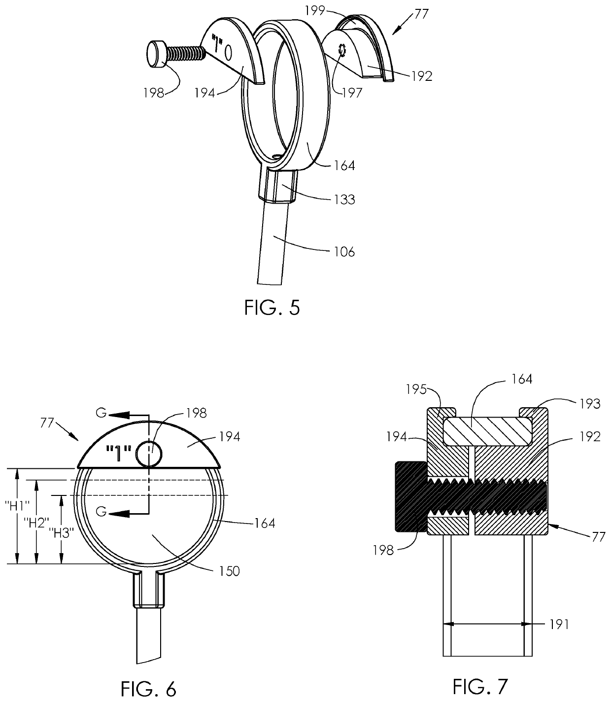
[0016]An alternate embodiment 77 is shown in FIGS. 5-7 that comprises the annular member 164 connected to a syringe plunger shaft 106 via a shoulder 133 and has a lateral width 191, around which facing spacers 192, 194 are applied to together grip the annular member 164 when a screw 198 engages a threaded opening 197 (or other device) draws the spacers 192, 194 together and apply a compression force to the annular member 164. Typically, the facing spacers 192, 194 form a recess e.g. 199, by radially extending members 193, 195 that extend radially past, and as shown in cross section G of FIG. 7, partially surround the annular member 164. According to embodiments of the present invention, spacers 192, 194 may have a larger inwardly facing dimension to intrude further into the open area 150 to provide different interior spacings, e.g. H1, H2, H3, etc. as desired.
PUM
 Abstract
Description
Claims
Application Information
 - R&D
- Intellectual Property
- Life Sciences
- Materials
- Tech Scout
- Unparalleled Data Quality
- Higher Quality Content
- 60% Fewer Hallucinations
Browse by: Latest US Patents, China's latest patents, Technical Efficacy Thesaurus, Application Domain, Technology Topic, Popular Technical Reports.
© 2025 PatSnap. All rights reserved.Legal|Privacy policy|Modern Slavery Act Transparency Statement|Sitemap|About US| Contact US: help@patsnap.com


