Differential Analog Multiplier-Accumulator

Pending Publication Date: 2022-06-30
CEREMORPHIC INC
View PDF0 Cites 2 Cited by
  • Summary
  • Abstract
  • Description
  • Claims
  • Application Information

AI Technical Summary

Problems solved by technology

Additionally, prior art multipliers relied on synchronous, clocked stages t

Method used


Image

  • Differential Analog Multiplier-Accumulator
  • Differential Analog Multiplier-Accumulator
  • Differential Analog Multiplier-Accumulator

Examples


Example

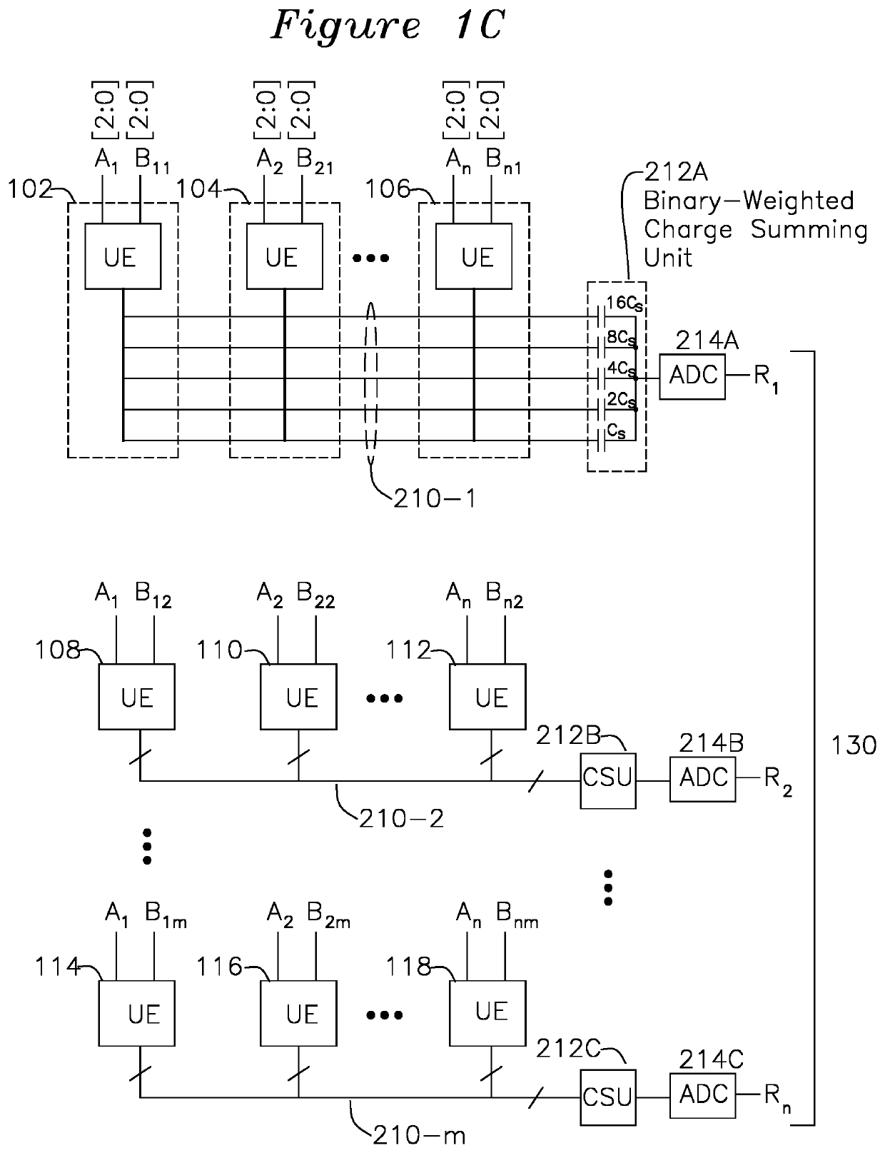
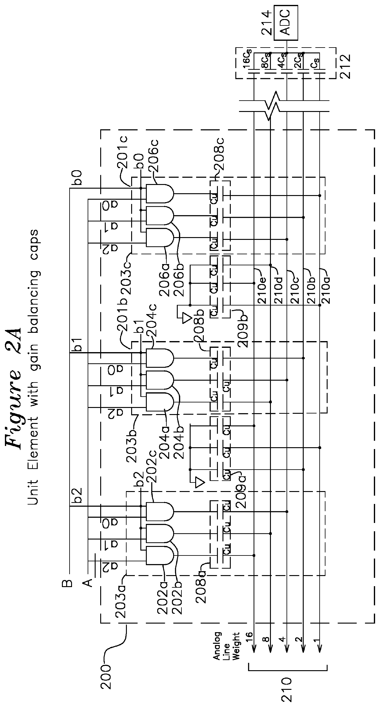
[0040]By way of convention, in the present application, similar reference numbers on different figures indicate the same element or function. Where a function is performed by individual elements, the suffix a, b, c etc may be appended as appears in the drawings, whereas the elements taken as a whole are understood to be without suffix, so for example unit element 201 or analog charge bus 210 are understood to refer to the entire structure when a suffix a, b, c, etc are not present.

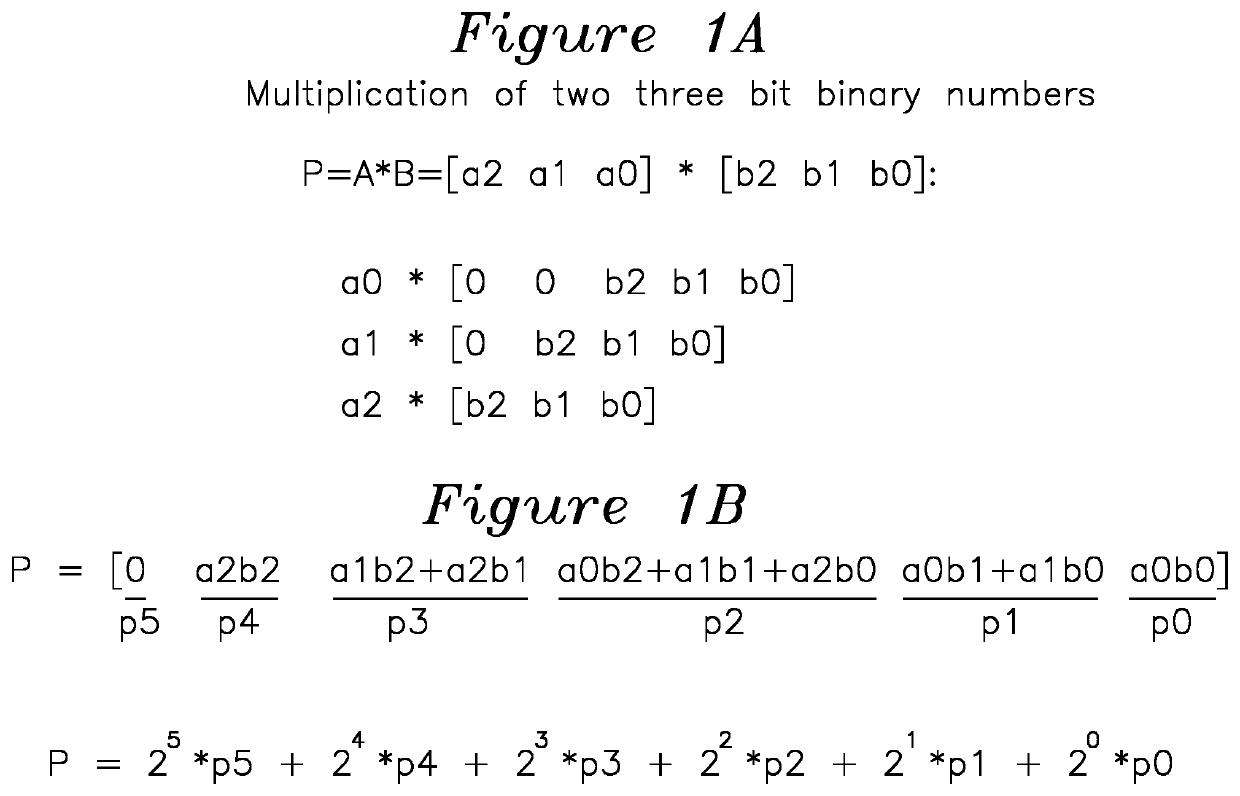
[0041]FIGS. 1A and 1B show an example expansion for multiplication of two 3 bit binary numbers. This may also be described as the partial product expansion:

[0042]p0[2:0]={a[0]&b[2], a[0]&b[1], a[0]&b[0]}

[0043]p1[2:0]={a[1]&b[2], a[1]&b[1], a[1]&b[0]}

[0044]p2[2:0]={a[2]&b[2], a[2]&b[1], a[2]&b[0]}

[0045]which can be rearranged as:

P=1*p0[0]+2*(p0[1]+p1[0])+4*(p0[2]+p1[1]+p2[0])+8*(p1[2]+p2[1])+16*(p2[2])

[0046]In one example embodiment, the binary charge summing may be performed by selection of relative capaci...


PUM


Abstract

A differential multiplier-accumulator accepts A and B digital inputs and generates a dot product P by applying the bits of the A input and the bits of the B inputs to respective positive and negative unit elements comprised of groups of AND gates coupled to charge transfer lines through a capacitor Cu. Each positive and negative unit element receives one bit of the B input applied to all of the AND gates of the unit element, and each positive and negative unit element having the bits of A applied to each associated AND gate input of each unit element. The AND gates are coupled to charge transfer lines through a capacitor Cu, and the charge transfer lines couple to binary weighted charge summing capacitors and to an analog to digital converter to generate a digital output product. The charge transfer lines may span multiple unit elements.

Description

FIELD OF THE INVENTION[0001]The present invention relates to a multiplier-accumulator. In particular, the invention relates to an asynchronous multiplier operable to be cascaded and configured to operate as a multiplier-accumulator, which accepts digital inputs and generates a summed analog output which can be digitized to form a digital output representing a sum of multiplication products.BACKGROUND OF THE INVENTION[0002]The expanded use of Artificial Intelligence (AI) software applications has created a need for scalable hardware multiplier-accumulators for acceleration of software algorithms used in machine learning (ML). An n×n multiplier increases in gate complexity as n2, and large numbers of adders are further needed for multiply-accumulate operations. Additionally, prior art multipliers relied on synchronous, clocked stages to operate, and the clocked operation results in increased power dissipation.[0003]For example, in machine learning applications, it is often desired to ...

Claims


Application Information

Patent Timeline
IPC IPC(8): H03M3/04G06F7/544
CPCH03M3/04G06F7/5443G06F2207/4824G06G7/16
Inventor KRAEMER, MARTINBOESCH, RYANXIONG, WEI
Owner CEREMORPHIC INC
Why Eureka
Try Eureka