Device for Switching Operating Modes of a Dynamic Pylon

Pending Publication Date: 2022-07-07
KORIUSHENKOV NIKOLAI A
View PDF0 Cites 0 Cited by
  • Summary
  • Abstract
  • Description
  • Claims
  • Application Information

AI Technical Summary

Problems solved by technology

The disadvantages of the device under the patent CN107875609 include the manufacturing that requires to perform large amount of machine works and to make qualification assemble.
The disadvantage of technical solution as per the Patent FR3041884 is a complex process of switching the operating modes of a dynamic pylon.
When pylon is in the static operating mode the rods are located simultaneously both in the holes of the first ring and in the holes of the cap of the lower support and provide a mechanical obstacle to the rotation of the pole.
In the situation obtained by this method the rods are located simultaneously both in the holes of the first ring and in the holes of the cap of the lower support and

Method used


Image

  • Device for Switching Operating Modes of a Dynamic Pylon
  • Device for Switching Operating Modes of a Dynamic Pylon
  • Device for Switching Operating Modes of a Dynamic Pylon

Examples


example 3

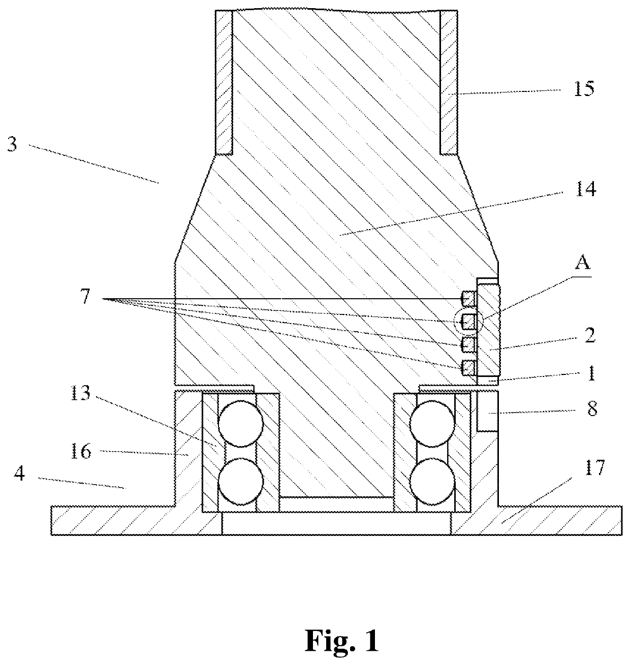
[0111] FIG. 6 shows an axial section of a part of the dynamic pylon with the device for switching over the operating modes when the lower support 4 of the pylon is located on the lower bearing surface (for example, on the stage floor). Shaft 14 and pipe 15 are connected with an interference fit installation method and comprise the pole 3. Shaft 14 can comprise of a few details and be dismountable. The other details of the pole 3 of the pylon are not shown in FIG. 6. The bushing 16 and disc 17 comprise of the support 4 and joined together with screw connections. The screw connections and other details of the lower support are not shown in FIG. 6. Bearing 13 is installed in the bushing 16 and shaft 14 is installed into inner ring of the bearing 13.

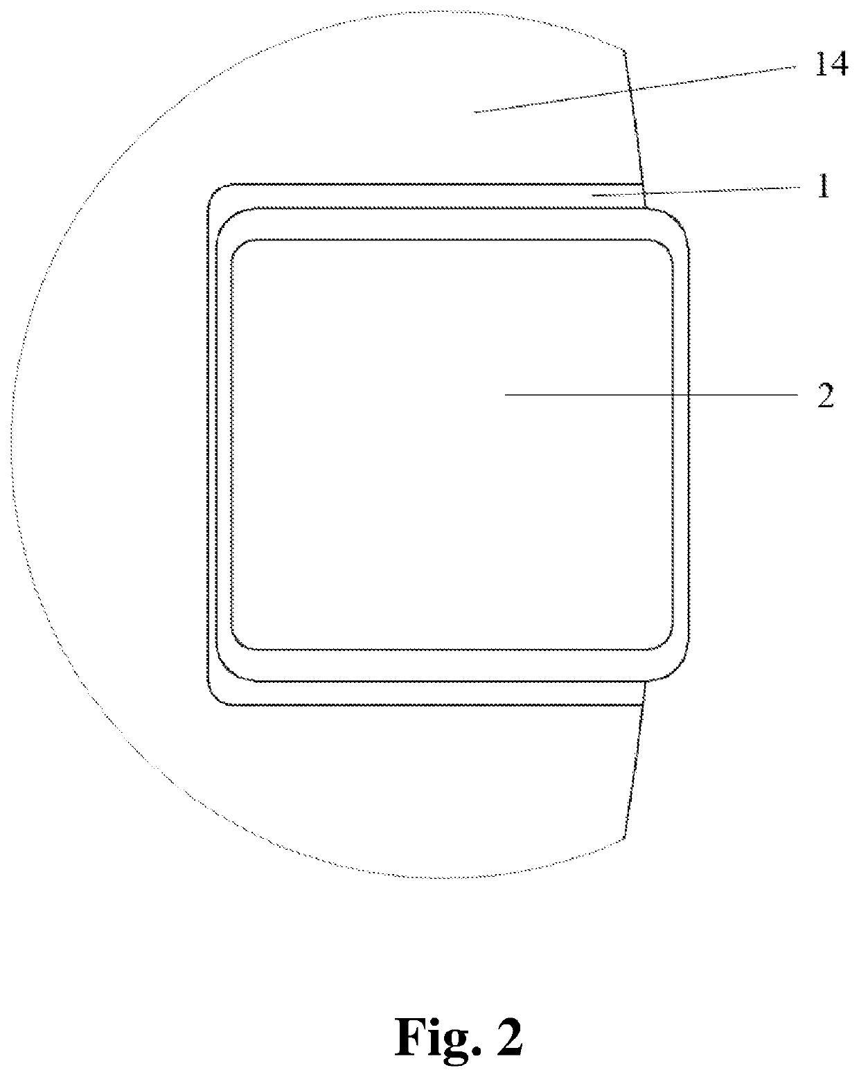
[0112]Device for switching over the operating mode of a dynamic pylon comprises of:[0113]The latch 2 made as a pin of round cross-section featured with handle 6;[0114]The shaft 14 of the pole 3 with the main recess 1 made as a blind hole of ...

example 6

[0159] FIG. 12 repeats the view of the axial section of a part of the dynamic pylon with the device for switching over its operating modes shown in FIG. 9. Design description and operational features of the device for switching over the operating modes of a dynamic pylon shown in FIG. 9 remain in force for the device shown in FIG. 12, except for one constructional and two operational features.

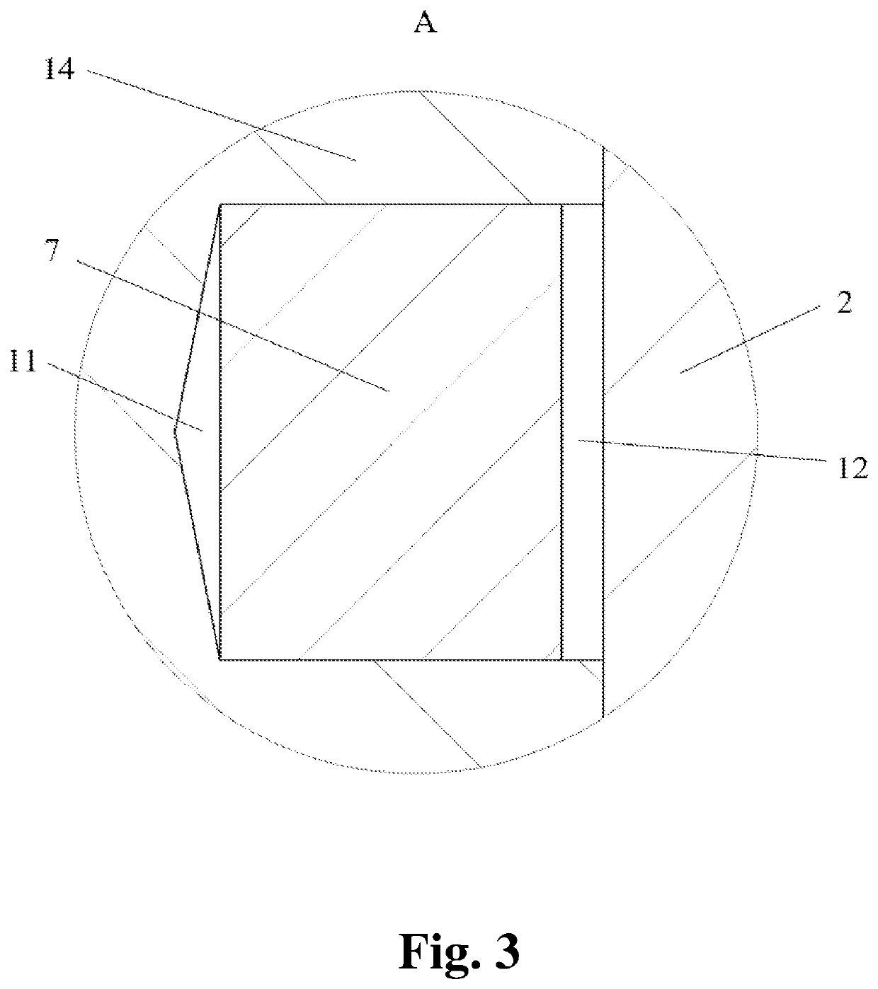
[0160]Construction feature is that the additional permanent magnet 7 (lower in FIG. 12)—a monolithic cylindrical detail made of magnetically hard material is installed with glue on the lower end of the latch 2 in a cavity 11 formed as a hole of a circular cross-section.

[0161]In this case an additional permanent magnet 7, as the first member of the second magnetic lock, the latch 2 in the cavity 11 at the lower end of which this magnet 7 is installed, as the second member of the second magnetic lock, and the ring 19 of the support 4 made at least partially of magnetically soft material—steel as ...


PUM


Abstract

Device for switching over the operating mode of a dynamic pylon for dances comprises as follows: the latch (2) at least one detail of pylon assemble with main recess (1) for the latch (2) at least one detail of another pylon assemble with counter-recess (8) for the latch (2) one magnet lock comprising at least one permanent magnet (7), whereas the main recess (1) for the latch (2) performed opened from the side of its lateral wall towards the outer space around the pylon detail wherein the main recess (1) is located, whereas the latch (2) is a member of the magnetic lock (the second or the third one). Switching over the mode of pylon operation is possible without interrupting the performance of exercises.

Description

FIELD OF THE INVENTION[0001]The invention relates to gymnastic equipment and more specifically to pylons intended for performance of gymnastic exercises and dances by artists.[0002]There are static and dynamic pylons. Dynamic pylon comprises of the following assemblies: a pole and one or two supports. The pole and the supports are interconnected with a possibility of the pole rotation typically using one or more bearings. Moving assembly a “Pole” of the dynamic pylon provides a pillar of support for a performer of gymnastic exercises on the pole and can comprise of different combinations of multiple details, such as pipe, shaft, bushing, screw, nut and others. Static Support assembly of a dynamic pylon is intended for installation and retaining the pole at the operational location and can comprise of different combinations of various details such as disc, bushing, axle, and other details. Dynamic pylons can function both in static mode when the pylon pole cannot rotate and dynamic m...

Claims


Application Information

Patent Timeline
IPC IPC(8): A63B9/00
CPCA63B9/00A63B2209/08A63B2244/225A63B71/028A63B21/16
Inventor KORIUSHENKOV, NIKOLAI A.
Owner KORIUSHENKOV NIKOLAI A
Why Eureka
Try Eureka