Plate heat exchanger

a heat exchanger and plate technology, applied in the direction of reinforcement means, lighting and heating apparatus, laminated elements, etc., can solve the problems and reducing the efficiency of the plate heat exchanger. , to achieve the effect of reducing the stress in the reinforcement joints and facilitating bonding

Inactive Publication Date: 2015-03-19
ALFA LAVAL CORP AB
View PDF7 Cites 3 Cited by
  • Summary
  • Abstract
  • Description
  • Claims
  • Application Information

AI Technical Summary

Benefits of technology

[0023]According to one embodiment of the inventive plate heat exchanger, the reinforcement plate has projections on a side arranged to face the outermost heat transfer plate. Each of these projections is received in a respective one of the recesses of the outermost heat transfer plates. Thus, this embodiment offers a guidance for correct positioning of the reinforcement plate on the stack of heat transfer plates. At the same time a close arrangement, and thereby an easy bonding, of the reinforcement plate and the outermost heat transfer plate is enabled.
[0024]The plate heat exchanger may further comprise a third number of first inserts arranged between the peripheral portions of the outermost and the second outermost heat transfer plates. The first inserts may be arranged along two opposite edges of the heat transfer plates, aligned with the reinforcement joints. Each of the first inserts may be bonded to one or both of the outermost and second outermost heat transfer plates by a permanent first insert joint. By the provision of the first inserts, the stress in the reinforcement joints may be reduced.

Problems solved by technology

However, for applications where the pressure outside the heat exchanger is higher than the pressure inside the free-flow channels, there is a risk of deformation, more particularly compression, of at least the outermost free-flow channel.
Naturally, this could negatively effect the performance of the plate heat exchanger.
As compared to a “conventional” un-free, or obstructed, flow path where support points between the heat transfer plates are present, a free-flow path is weaker and more easily deformed under certain conditions.
This pressure relationship is necessary in some plate heat exchanger applications but could lead to deformation of the free-flow path if the reinforcement plate was not present.
Naturally, this could jeopardize the performance of the plate heat exchanger.

Method used


Image

  • Plate heat exchanger
  • Plate heat exchanger
  • Plate heat exchanger

Examples


Embodiment Construction

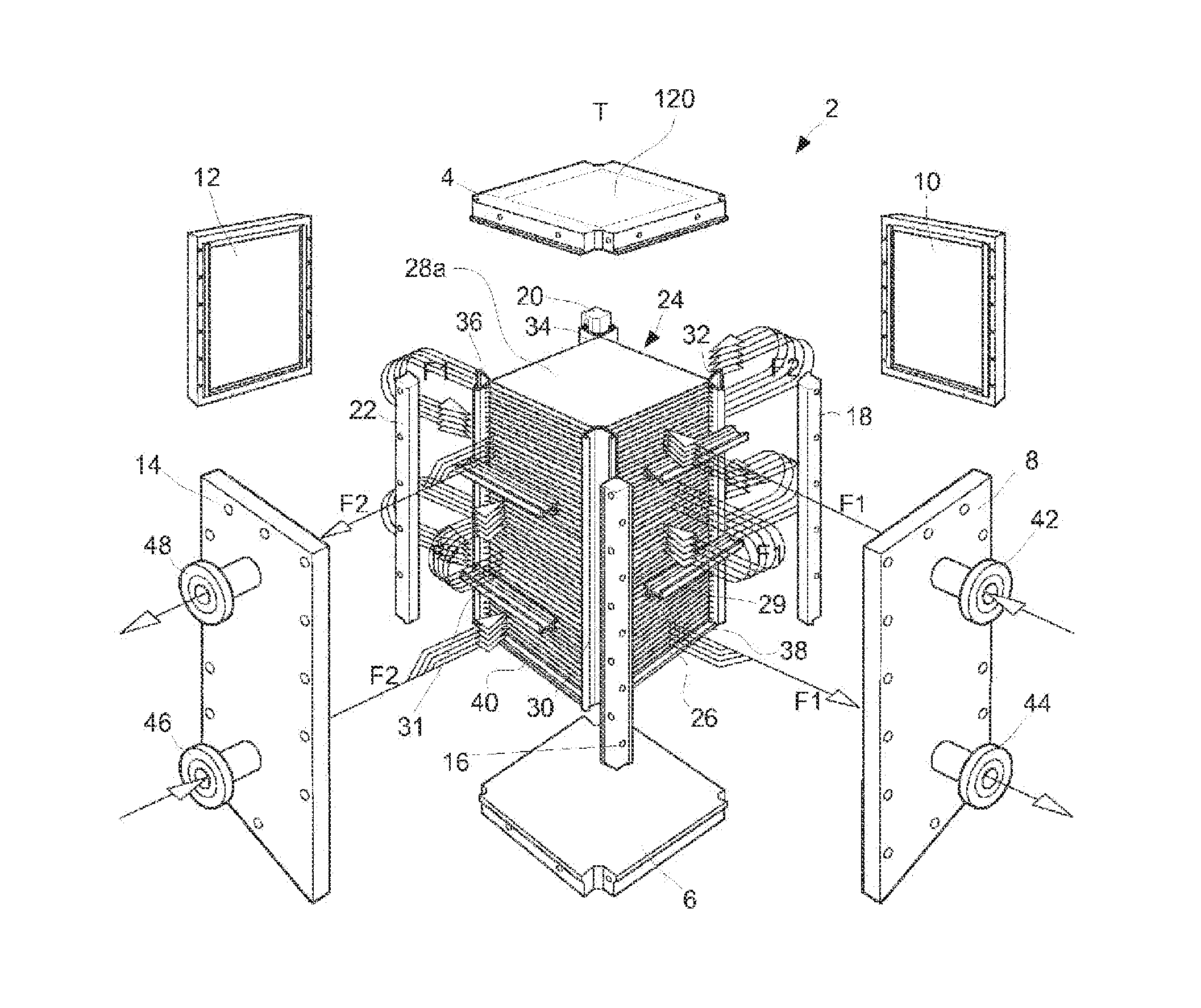
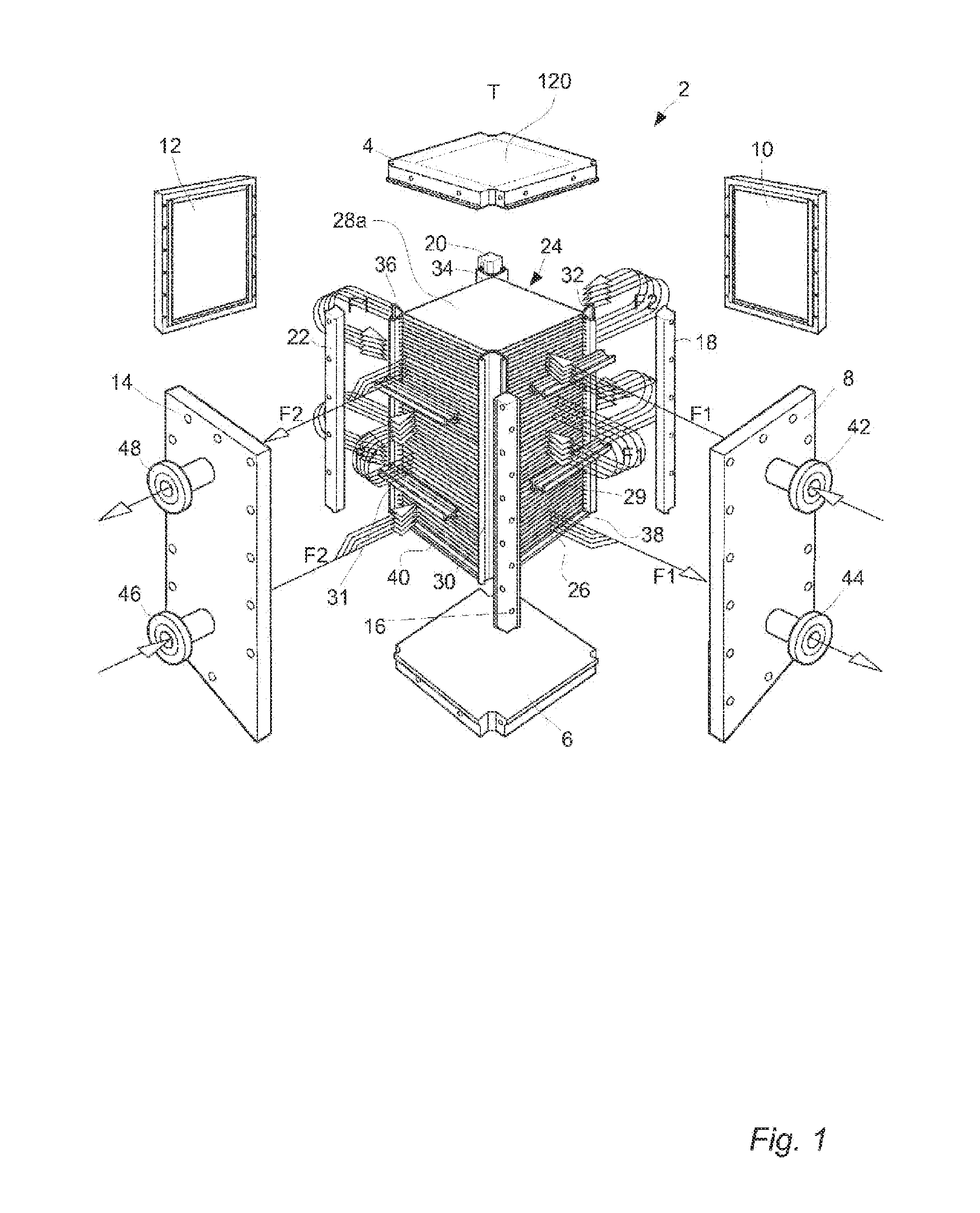
[0048]With reference to FIG. 1 a plate heat exchanger 2 of a block-type is shown. The plate heat exchanger 2 comprises a first frame plate or top head 4, a second frame plate or bottom head 6 and four side panels 8, 10, 12 and 14 that are bolted together with four corner girders 16, 18, 20 and 22 to form a parallelepiped shaped enclosure of the assembled plate heat exchanger 2. A stack 24 of aligned essentially rectangular heat transfer plates 26 of stainless steel and two rectangular reinforcement plates 28 of stainless steel (of which only one denoted 28a can be seen in FIG. 1) are arranged within the enclosure. The reinforcement plates 28 are aligned with the heat transfer plates 26 and attached to a respective end of the stack 24. Conventional baffles 29 and 31 are connected to sides of the stack 24 of heat transfer plates 26. The heat transfer plates, reinforcement plates and baffles will be further discussed below.

[0049]Four side linings 30, 32, 34 and 36 arranged to face a re...


PUM


Abstract

A plate heat exchanger includes first and second frame plates, and a stack of heat transfer plates. Each heat transfer plate has a peripheral portion encircling a center portion. The heat transfer plates are arranged in pairs between the first and second frame plates, and formed between the pairs of heat transfer plates is a first flow path for a first fluid and a second flow path for a second fluid. One of the first and second flow paths is a free-flow path along which center portions of the heat transfer plates are completely separated from each other. A reinforcement plate is thicker than the heat transfer plates and has a center portion encircled by a peripheral portion. The reinforcement plate is arranged between the first frame plate and the stack of heat transfer plates. Permanent reinforcement joints each bond together the reinforcement plate and an outermost heat transfer plate.

Description

TECHNICAL FIELD[0001]The invention relates to a plate heat exchanger comprising a first frame plate, a second frame plate and a stack of heat transfer plates. The heat transfer plates each have a center portion and a peripheral portion encircling the center portion. Further, the heat transfer plates are arranged in pairs between the first and the second frame plate, a first flow path for a first fluid being formed between the heat transfer plates of the pairs and a second flow path for a second fluid being formed between the pairs of heat transfer plates. One of the first and second flow paths is a free-flow path along which the center portions of the heat transfer plates are completely separated from each other.BACKGROUND ART[0002]Today several different types of plate heat exchangers exist, which are employed in various applications depending on their type. One certain type of plate heat exchanger is assembled by bolting a top head, a bottom head and four side panels to a set of c...

Claims


Application Information

Patent Timeline
Patent Type & Authority Applications(United States)
IPC IPC(8): F28F3/04
CPCF28F3/04F28F3/046F28D9/0037F28F2225/00F28D9/00F28D9/02F28F3/00F28F3/02F28F3/048
Inventor BLOMGREN, RALFNOEL-BARON, OLIVIER
Owner ALFA LAVAL CORP AB
Why Eureka
Try Eureka