System and apparatus for energy conversion

a technology of energy conversion and system, applied in the direction of engine cooling apparatus, machine/engine, hot gas positive displacement engine plant, etc., can solve the problems of inefficient combustion, inefficient heat exchanger, and inability to meet the needs of the customer,

Pending Publication Date: 2022-07-07
HYLIION HLDG CORP
View PDF5 Cites 0 Cited by
  • Summary
  • Abstract
  • Description
  • Claims
  • Application Information

AI Technical Summary

Problems solved by technology

Power generation and distribution systems are challenged to provide improved power generation efficiency and / or lowered emissions.
Furthermore, power generation and distribution systems are challenged to provide improved power output with lower transmission losses.
However, closed cycle engine arrangements, such as Stirling engines, are challenged to provide relatively larger power output or power density, or improved efficiency, relative to other engine arrangements.
Closed cycle engines may suffer due to inefficient combustion, inefficient heat exchangers, inefficient mass transfer, heat losses to the environment, non-ideal behavior of the working fluid(s), imperfect seals, friction, pumping losses, and / or other inefficiencies and imperfections.

Method used


Image

  • System and apparatus for energy conversion
  • System and apparatus for energy conversion
  • System and apparatus for energy conversion

Examples


Embodiment Construction

[0042]Reference now will be made in detail to embodiments of the disclosure, one or more examples of which are illustrated in the drawings. Each example is provided by way of explanation of the disclosure and not limitation. In fact, it will be apparent to those skilled in the art that various modifications and variations can be made in the present disclosure without departing from the scope of the disclosure. For instance, features illustrated or described as part of one embodiment can be used with another embodiment to yield a still further embodiment. In another instance, ranges, ratios, or limits associated herein may be altered to provide further embodiments, and all such embodiments are within the scope of the present disclosure. Unless otherwise specified, in various embodiments in which a unit is provided relative to a ratio, range, or limit, units may be altered, and / or subsequently, ranges, ratios, or limits associated thereto are within the scope of the present disclosure...


PUM


Abstract

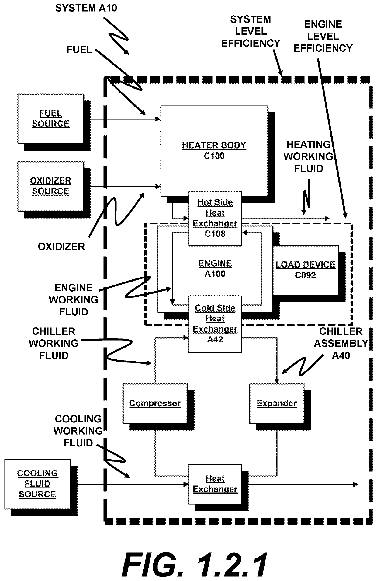
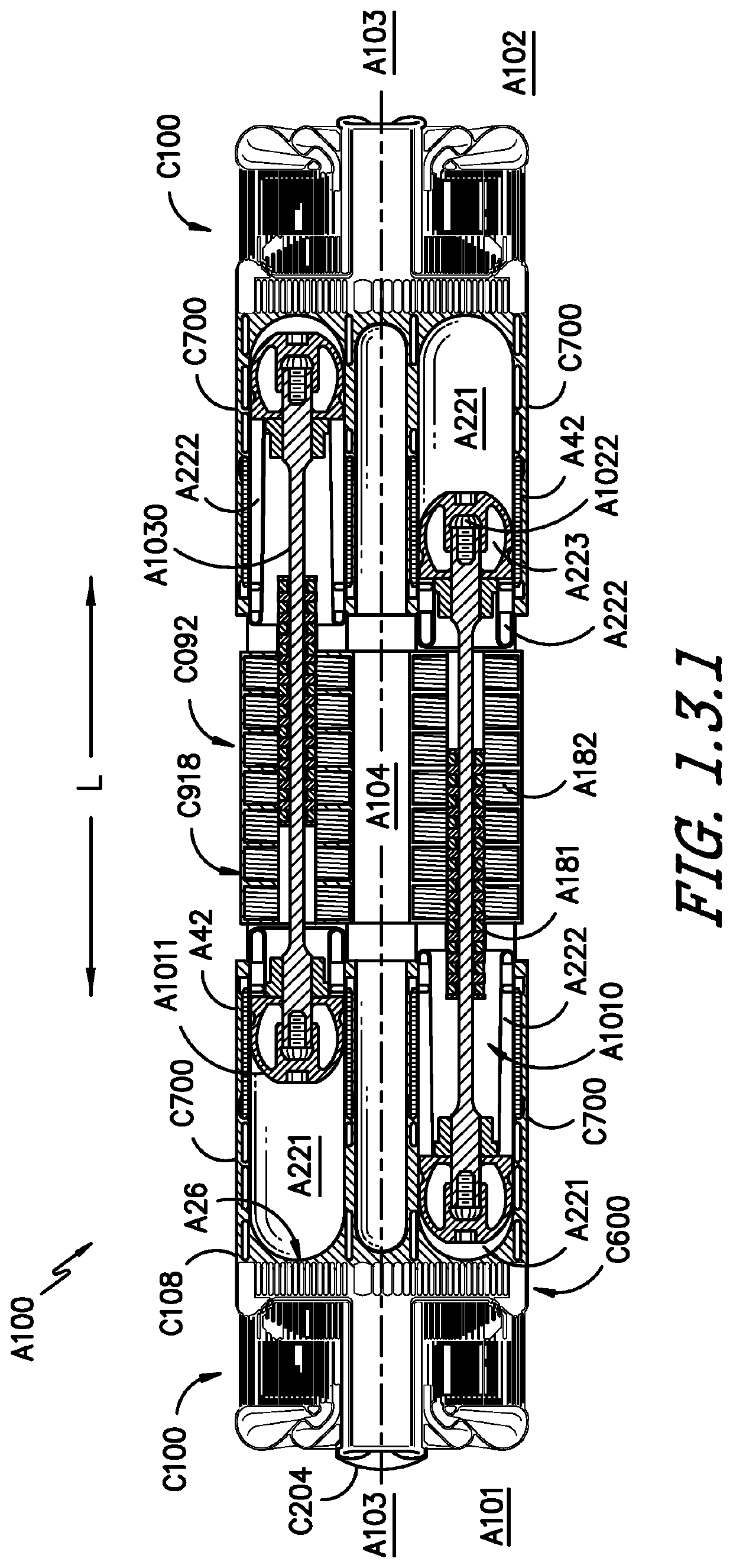
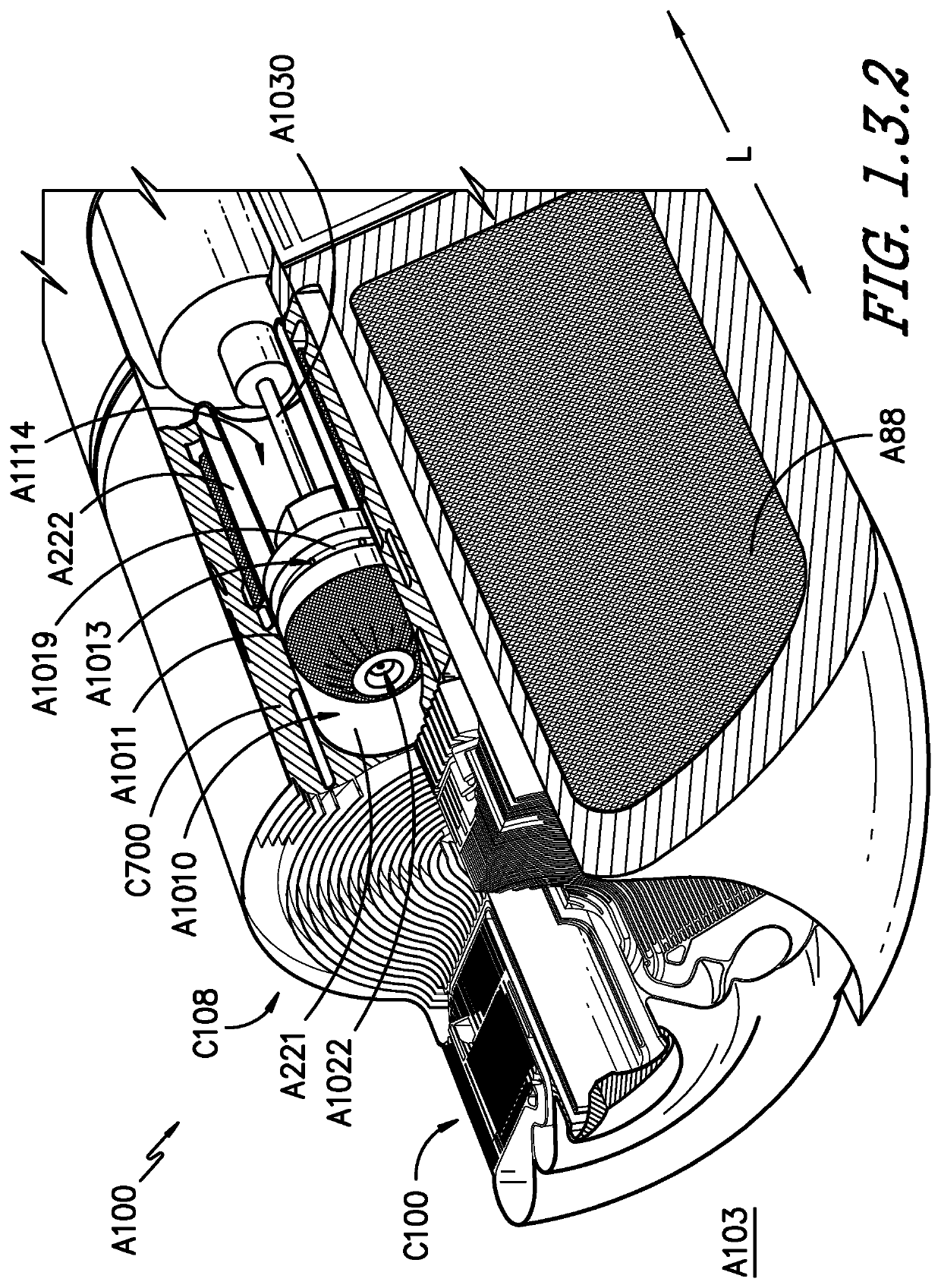
A system for energy conversion including a closed cycle engine containing a volume of working fluid is provided. The engine includes a double-ended piston assembly including a pair of pistons coupled to a connection member. An expansion chamber is separated from a compression chamber by the piston. The engine defines an outer end and an inner end relative to a lateral extension of the piston assembly. A heater body is positioned thermally proximal to the expansion chamber and thermally distal to the compression chamber, and the heater body is positioned at the outer end of the engine. A load device is operably coupled to the piston assembly at the inner end of the engine. The load device is positioned between the pair of pistons of the piston assembly.

Description

CROSS-REFERENCE TO RELATED APPLICATIONS[0001]The present application claims the benefit of the earliest available effective filing date and is a continuation application of U.S. patent application Ser. No. 16 / 418,129 titled “SYSTEM AND APPARATUS FOR ENERGY CONVERSION” having a filing date of May 21, 2019 and which is incorporated herein by reference in its entirety.FIELD[0002]The present subject matter relates generally to energy conversion systems, power generation systems, and energy distribution systems. The present subject matter additionally relates to heat exchangers and heat exchanger systems. The present subject matter further relates to piston engine assemblies, such as closed-cycle engine systems. The present subject matter still further relates to systems and methods for control or operation of one or more systems of the present subject matter herein.BACKGROUND[0003]Power generation and distribution systems are challenged to provide improved power generation efficiency an...

Claims


Application Information

Patent Timeline
Patent Type & Authority Applications(United States)
IPC IPC(8): F02G1/055F02G1/044F02G1/057
CPCF02G1/055F02G1/044F02G2255/00F02G2270/40F02G2256/04F02G1/057F02G1/0435F02G2244/52F02G2256/50F02G2280/10
Inventor MOOK, JOSHUA TYLERGANSLER, MICHAEL THOMASWAUN, SCOTT DOUGLASVANDEVOORDE, KEVIN MICHAELAKWARA, AIGBEDIONNOTARNICOLA, MICHAEL ROBERTBELLARDI, JASON JOSEPHSENNOUN, MOHAMMED EL HACINOSAMA, MOHAMED
Owner HYLIION HLDG CORP
Why Eureka
Try Eureka