X-ray imaging apparatus

a technology of x-ray imaging and x-ray, which is applied in the field of x-ray imaging apparatus, can solve the problems of increasing the irradiation dose of x-rays, the disadvantage of increasing the scattering of x-rays, and the image quality of the resulting image deteriorating, so as to reduce the burden on the operator

Pending Publication Date: 2022-07-21
SHIMADZU CORP
View PDF23 Cites 0 Cited by
  • Summary
  • Abstract
  • Description
  • Claims
  • Application Information

AI Technical Summary

Benefits of technology

[0011]The X-ray imaging apparatus according to one aspect of the present invention includes, as described above, the control unit configured to perform control of a position adjustment operation for adjusting a position of the X-ray detector such that a distance from a surface of a subject model to the X-ray detector becomes a predetermined distance. Thus, by performing the control of the position adjustment operation, the X-ray detector is arranged at the position that is the predetermined distance from the surface of the X-ray detector. Therefore, it is possible to bring the X-ray detector closer to the subject, based on the distance between the subject and the X-ray detector, taking into account the shape of the subject placed on the bed rather than the distance between the X-ray detector and the bed.
[0012]Further, it is possible to bring the X-ray detector closer to the subject up to the predetermined distance without moving the X-ray detector by the operator. As a result, it is possible to suppress that the distance between the subject and the X-ray detector becomes larger than the predetermined distance while suppressing the increase in the burden on the operator. It should be noted that the predetermined distance denotes a concept including the case where the distance is 0 (zero). That is, the predetermined distance may also include a distance at which the X-ray detector comes into contact with the surface of the subject model.

Problems solved by technology

However, increasing of irradiation dose of X-rays has the disadvantage of increasing scattered X-rays.
When scattered X-rays are increased, there is a disadvantage in that the image quality of the resulting image deteriorates.
However, there is a disadvantage in that the burden on the operator increases because the X-ray detector needs to be moved manually each time the imaging position is changed.

Method used


Image

  • X-ray imaging apparatus
  • X-ray imaging apparatus
  • X-ray imaging apparatus

Examples


Embodiment Construction

[0033]Hereinafter, some embodiments in which the present invention is embodied will be described with reference to the attached drawings.

[0034]Referring to FIG. 1 to FIG. 8, the configuration of an X-ray imaging apparatus 100 according to an embodiment of the present invention will be described.

(Configuration of X-Ray Imaging Apparatus)

[0035]First, referring to FIG. 1, the configuration of the X-ray imaging apparatus 100 according to an embodiment of the present invention will be described.

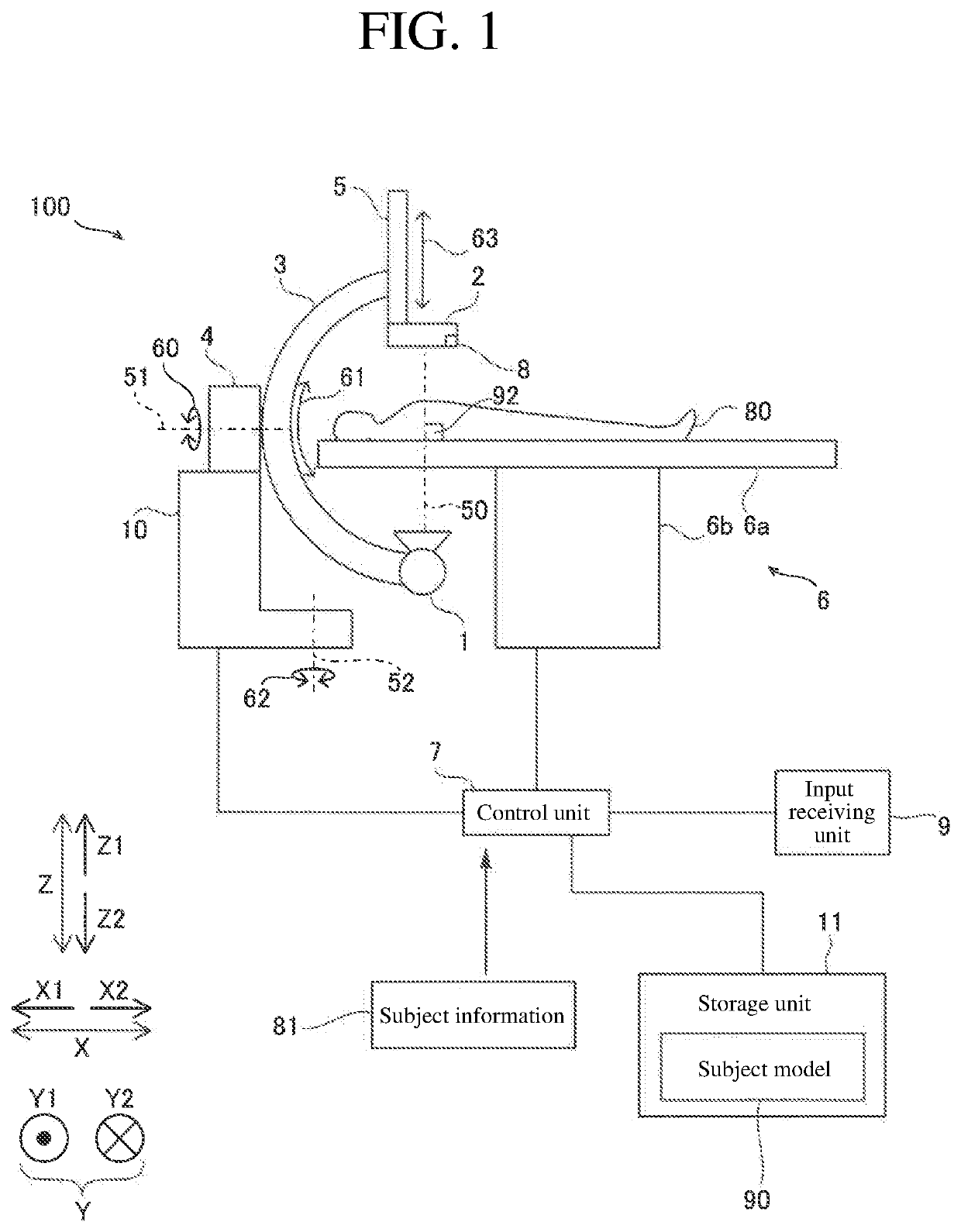
[0036]As shown in FIG. 1, the X-ray imaging apparatus 100 is provided with an X-ray source 1, an X-ray detector 2, an arm 3, an arm driving mechanism 4, an X-ray detector moving mechanism 5, a bed 6, and a control unit 7. Further, in this embodiment, the X-ray imaging apparatus 100 is further provided with a contact sensor 8. Further, in this embodiment, the X-ray imaging apparatus 100 is further provided with an input receiving unit 9. Further, in this embodiment, the X-ray imaging apparatus 100 ...


PUM


Abstract

This X-ray imaging apparatus includes an X-ray source, an X-ray detector, an arm, an arm driving mechanism, an X-ray detector moving mechanism, a bed, and a control unit. The control unit performs control of a position adjustment operation for adjusting a position of the X-ray detector such that a distance from a surface of a subject model serving as a model of a surface shape of the subject to the X-ray detector becomes a predetermined distance by moving the X-ray detector toward or away from the surface of the subject model.

Description

CROSS-REFERENCE TO RELATED APPLICATIONS[0001]This application claims priority to Japanese Patent Application No. 2021-006291, entitled “X-Ray Imaging Apparatus,” filed on Jan. 19, 2021, invented by ONODERA Hiroki, YOSHIDA Koki, HIROSE Dai, the entire contents of which is hereby incorporated by reference.BACKGROUND OF THE INVENTIONField of the Invention[0002]The present invention relates to an X-ray imaging apparatus, in particular to an X-ray imaging apparatus provided with an arm for holding an X-ray source and an X-ray detector.Description of the Background Art[0003]Conventionally, an X-ray imaging apparatus provided with an arm for holding an X-ray source and an X-ray detector is known. Such an X-ray imaging apparatus is disclosed, for example, in Japanese Unexamined Patent Application Publication No. 2001-95790.[0004]The X-ray imaging apparatus disclosed in Japanese Unexamined Patent Application Publication No. 2001-95790 is provided with a C-shaped arm, an X-ray tube, a flat pa...

Claims


Application Information

Patent Timeline
Patent Type & Authority Applications(United States)
IPC IPC(8): A61B6/00A61B6/04G01T1/161
CPCA61B6/4458G01T1/161A61B6/0407A61B6/544A61B6/44A61B6/54A61B6/4441A61B6/583A61B6/582
Inventor ONODERA, HIROKIYOSHIDA, KOKIHIROSE, DAI
Owner SHIMADZU CORP
Why Eureka
Try Eureka