
Lighting apparatus

a technology of lighting apparatus and light source, which is applied in the direction of lighting and heating apparatus, semiconductor devices for light sources, instruments, etc., can solve the problems of reducing the influence of light, and affecting the quality of images

Active Publication Date: 2022-07-21
M VISION
View PDF7 Cites 1 Cited by
  • Summary
  • Abstract
  • Description
  • Claims
  • Application Information

AI Technical Summary

Benefits of technology

The present invention provides a lighting apparatus that emits uniform light without shadow, providing soft dome lighting. It has a compact and thin design that saves space, and can obtain a bright and clear image with a light guide plate even if the dome lighting is larger than flat dome lighting. The invention solves issues with current dome lighting that has a decreased influence of light due to a size of a lighting hole and occupies a large space. The invention also solves issues with current flat dome lighting that causes light-emitting spots and pattern of a light guide plate is visible, degrading the quality of images.

Problems solved by technology

However, the dome lighting has a problem in that there occurs a zone (dark zone), in which an influence of light is decreased due to a size of a lighting hole (opening), and the dome lighting occupies a large space because the dome lighting has a larger volume than other types of lighting.
However, the flat dome lighting has a problem in that foreign substances included in a light guide diffusion plate cause light-emitting spots, and a pattern of the light guide plate may be visible, which degrades the quality of images.
However, this is not the case when the PCB angle is 90 degrees.
In addition, the present disclosure may solve the problem of the flat dome lighting that foreign substances included in a light guide diffusion plate cause light-emitting spots, and a pattern of the light guide plate may be visible, which degrades the quality of images.

Method used


Image

  • Lighting apparatus
  • Lighting apparatus
  • Lighting apparatus

Examples


Embodiment Construction

Problem in Related Art

[0054]In general, dome lighting is implemented by emitting uniform light at various angles using a dome-shaped lighting reflective plate. LED light is reflected in a hemispheric dome, such that soft and uniform light is emitted, and a test target is irradiated with the light.

[0055]The dome lighting is suitable for inspection of a product that creates a large amount of reflection and scattering, inspection of a curved or undulate surface, and inspection of detection of a uniform image of a rounded test target.

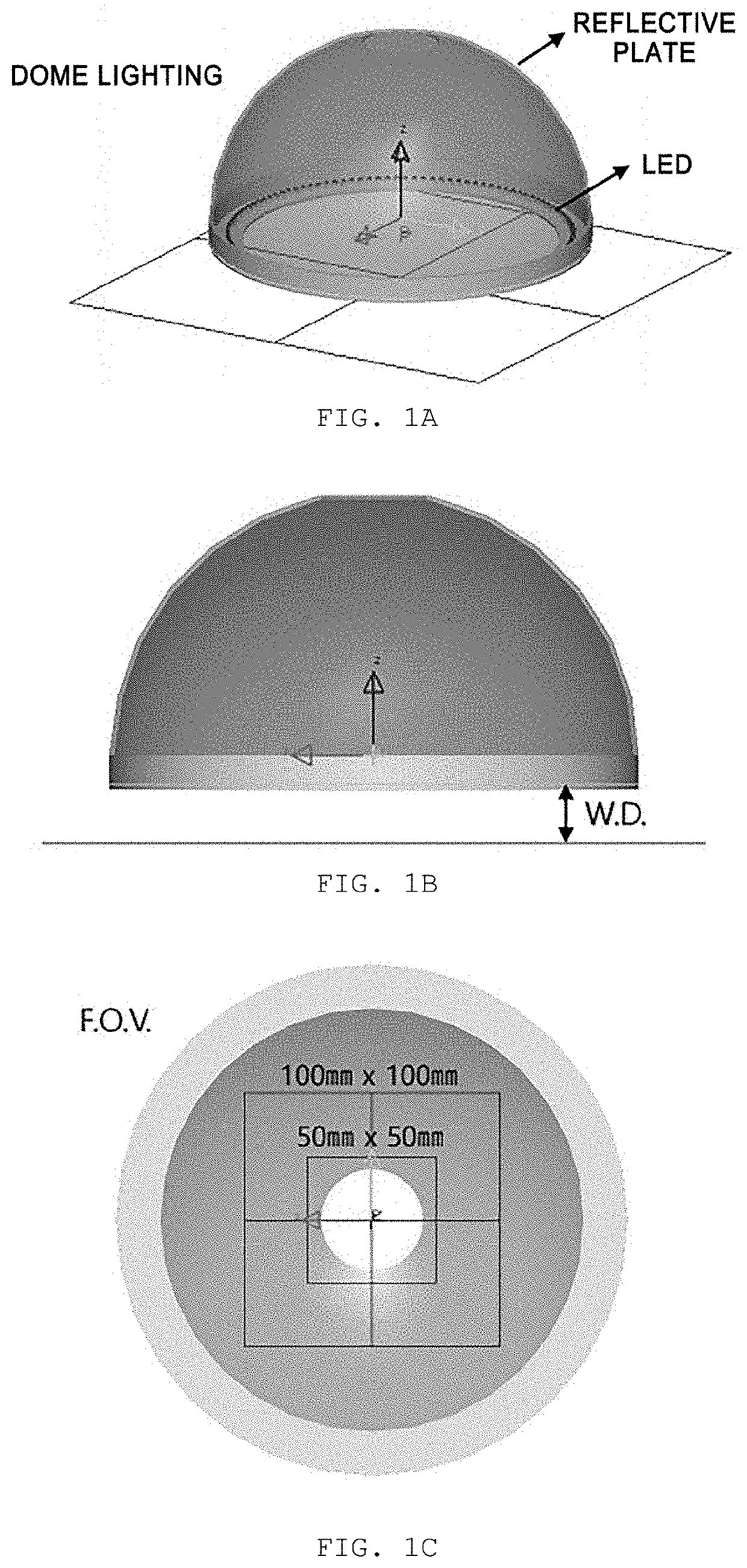
[0056]FIGS. 1A to 10 are views illustrating a structure of dome lighting in the related art.

[0057]Referring to FIGS. 1A to 10, a working distance (W.D.) and a field of view (F.O.V.) can be ascertained.

[0058]Examples of lighting utilized industrially may include dome lighting, coaxial lighting, flat dome lighting, and the like.

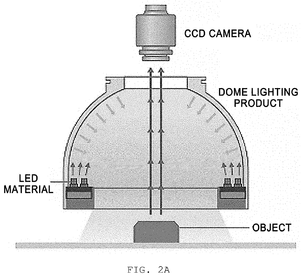
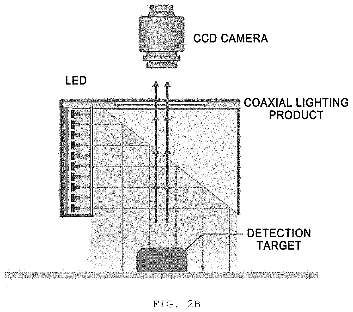
[0059]FIG. 2A is a view illustrating dome lighting in the related art; FIG. 2B is a view illustrating coaxial lighting in the related...


PUM


Abstract

The present disclosure relates to a lighting apparatus. A lighting apparatus according to an embodiment of the present disclosure includes: a dome structure including a first opening opened in a circular or polygonal shape at least partially in one surface thereof, and a second opening opened in a circular or polygonal shape at least partially in the other surface so as to be larger than the first opening; a plurality of reflective plates configured to connect one line the first opening and one line of the second opening; a PCB provided in the dome structure and disposed at a predetermined first angle based on a region of the other surface that excludes the second opening in the other surface of the dome structure; and a light source disposed on the PCB, in which light outputted at the first angle from the inside of the dome structure through the light source is reflected through at least one of the plurality of reflective plates, and the reflected light is emitted through the second opening to an object disposed at a lower end of the second opening and spaced apart from the dome structure.

Description

CROSS-REFERENCE TO RELATED APPLICATIONS[0001]This application claims the priority of Korean Patent Application No. 10-2021-0008154 filed on Jan. 20, 2021, in the Korean Intellectual Property Office, the disclosure of which is incorporated herein by reference.BACKGROUNDField[0002]The present disclosure relates to a lighting apparatus, and more particularly, to a lighting apparatus capable of emitting uniform light without shadow to provide soft dome lighting, having lightweight, compact, and thin design that saves a space, and obtaining a bright and clear image with a member of a light guide plate even though the dome lighting has a larger size than flat dome lighting.Description of the Related Art[0003]In general, dome lighting is implemented by emitting uniform light at various angles using a dome-shaped lighting reflective plate. LED light is reflected in a hemispheric dome, such that soft and uniform light is emitted, and a test target is irradiated with the light.[0004]The dome ...

Claims


Application Information

Patent Timeline
IPC IPC(8): F21V3/02F21V7/04F21V7/00F21V23/00
CPCF21V3/02F21V7/045F21Y2115/10F21V23/005F21V7/0066G03B15/06G01N21/8806G01N21/8851G01N21/95F21V7/041F21V7/05G01N2021/8816
Inventor LEE, GUYOUL
Owner M VISION
Learn More