
Expandable interbody spacer

a spacer and expandable technology, applied in the field of spine implants, can solve the problems of pain, compression or irritation, and achieve the effect of reducing distance and reducing distan

Active Publication Date: 2022-07-28
NEUROSTRUCTURES
View PDF10 Cites 1 Cited by
  • Summary
  • Abstract
  • Description
  • Claims
  • Application Information

AI Technical Summary

Benefits of technology

The spacer provides flexible and customizable expansion options, reducing the need for multiple sizes and minimizing surgical complexity, allowing for precise stabilization and alignment tailored to individual patient anatomy, thereby enhancing the effectiveness of spinal fusion procedures.

Problems solved by technology

In such cases, pain typically results from compression or irritation of spinal nerve roots arising from reduced spacing between adjacent vertebrae, a damaged disc and or misalignment of the spine resulting from the injury or degeneration.

Method used


Image

  • Expandable interbody spacer
  • Expandable interbody spacer
  • Expandable interbody spacer

Examples


Embodiment Construction

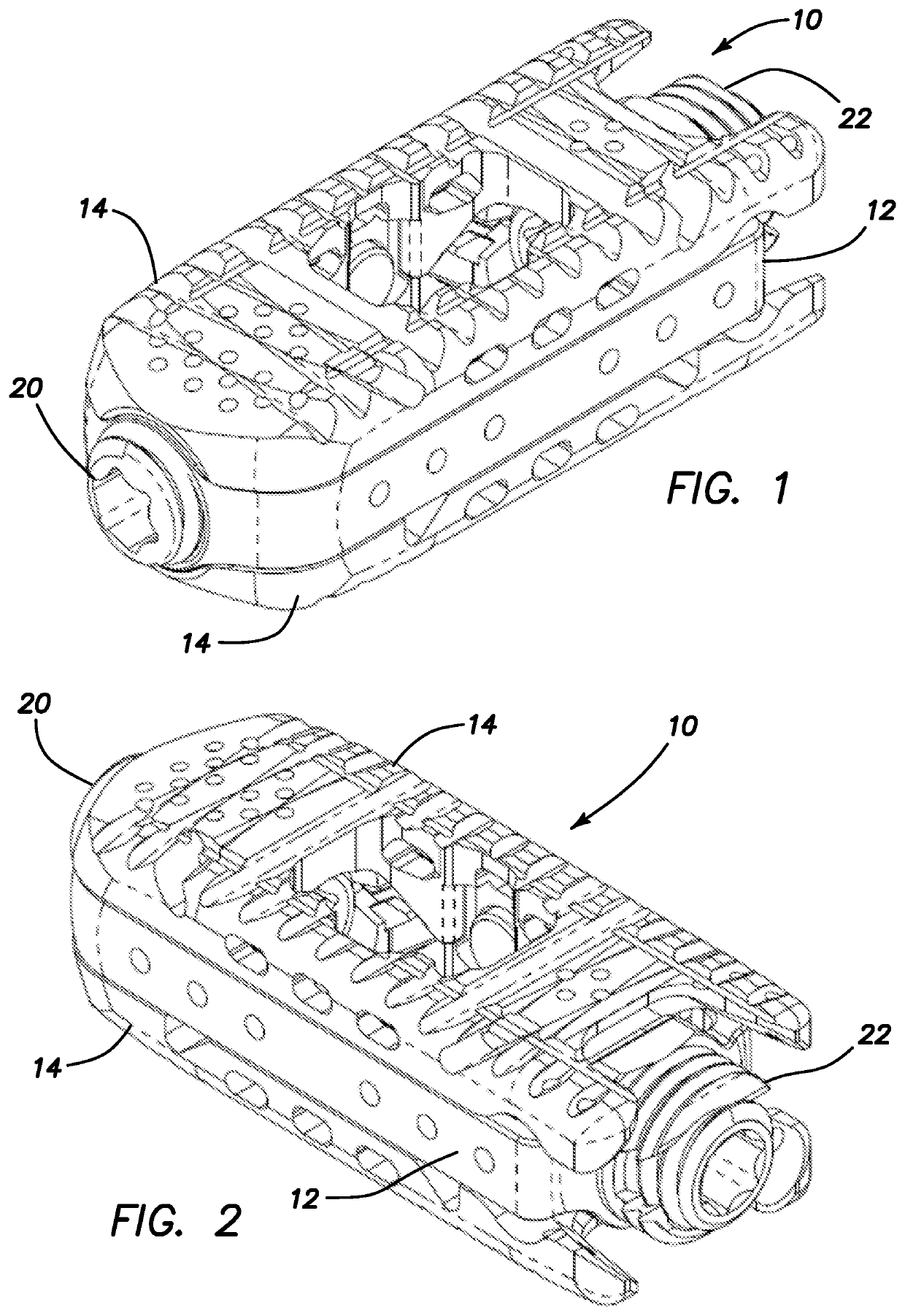
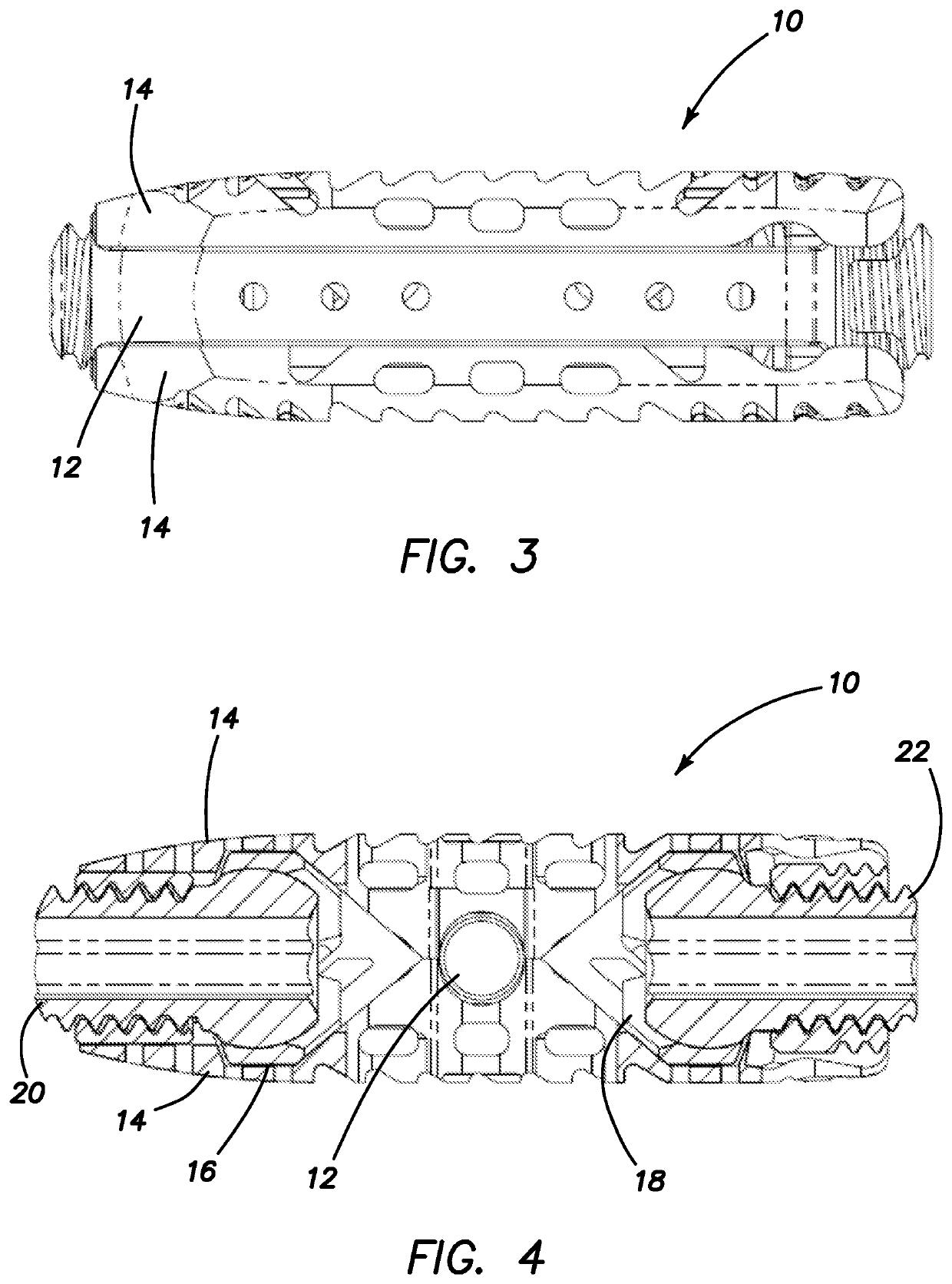
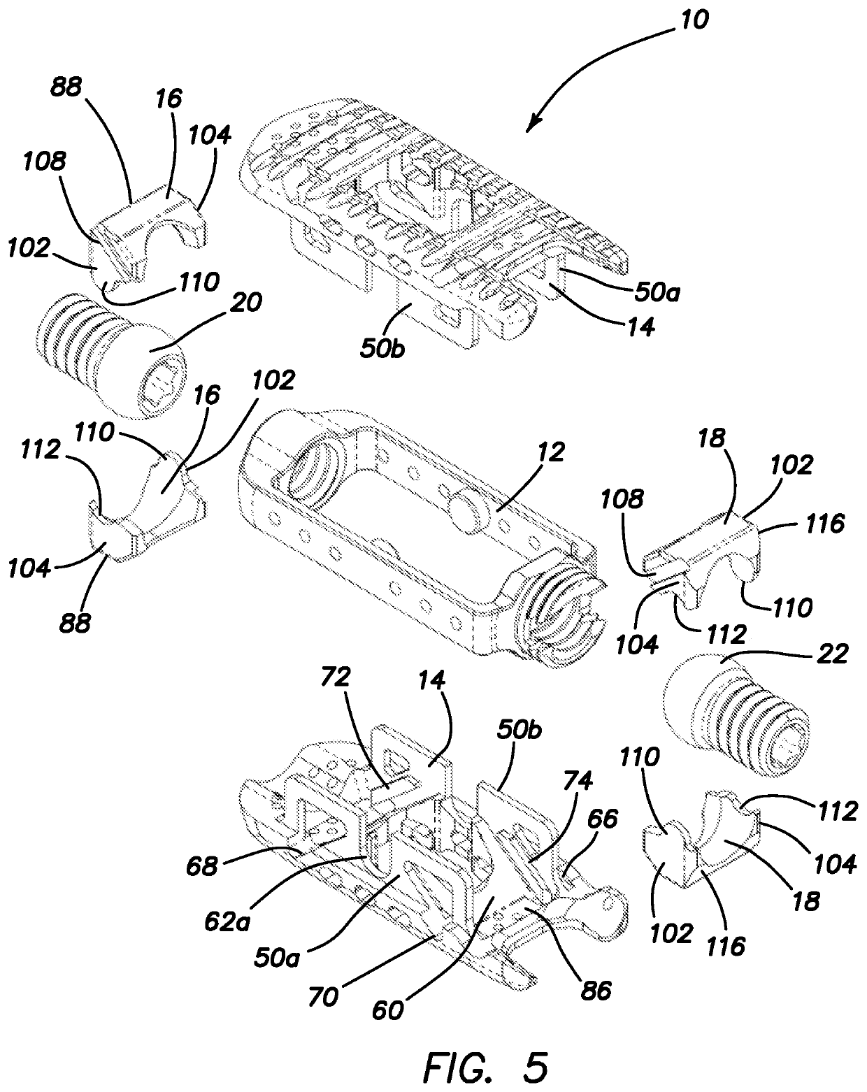
[0066]An expandable interbody spacer that is movable from an unexpanded configuration into a variety of expanded configurations including uniform parallel expansion, anterior angulation, posterior angulation and a combination of parallel expansion and anterior or posterior angulation is described below. FIGS. 1-4 depict an expandable interbody spacer 10 in an unexpanded configuration. The spacer 10 is typically used to stabilize or fuse vertebral bodies in the lumbar or other region of the spine. With particular reference to the exploded view of FIG. 5, the expandable interbody spacer 10 includes a housing 12, upper and lower endplates 14, an anterior actuator 16, a posterior actuator 18, an anterior drive screw 20, and a posterior drive screw 22. The expandable interbody spacer 10 is insertable into the disc space between two adjacent vertebral bodies from a posterior approach while in an unexpanded state illustrated in FIGS. 1-4. Generally, the unexpanded state is characterized by...


PUM


Abstract

An expandable interbody spacer for the spine is provided. The interbody spacer includes a housing, upper and lower endplates, an anterior actuator, a posterior actuator, an anterior drive screw, and a posterior drive screw. The anterior and posterior drive screws are independently or simultaneously rotated with respect to each other by a driver to wedge one or more of the anterior and posterior actuators between the endplates moving them into parallel and / or angular expansion.

Description

CROSS-REFERENCE TO RELATED APPLICATION[0001]This application is a continuation of co-pending U.S. patent application Ser. No. 16 / 894,308 filed on Jun. 5, 2020, entitled “Expandable interbody spacer” now issued as U.S. Pat. No. 11,304,817 incorporated herein by reference in its entirety.FIELD OF THE INVENTION[0002]This application relates generally to spinal implants, and in particular, expandable intervertebral spacers and fusion cages.BACKGROUND OF THE INVENTION[0003]Back pain can be caused by a variety of factors including but not limited to the rupture or degeneration of one or more intervertebral discs due to degenerative disc disease, spondylolisthesis, deformative disorders, trauma, tumors and the like. In such cases, pain typically results from compression or irritation of spinal nerve roots arising from reduced spacing between adjacent vertebrae, a damaged disc and or misalignment of the spine resulting from the injury or degeneration.[0004]Common forms of treating such pain...

Claims


Application Information

Patent Timeline
Patent Type & Authority Applications(United States)
IPC IPC(8): A61F2/44A61F2/46
CPCA61F2/442A61F2002/30593A61F2/447A61F2/4611A61F2002/30904A61F2/4455A61F2002/30331A61F2002/30383A61F2002/30405A61F2002/30476A61F2002/30507A61F2002/30538A61F2002/30556A61F2002/4627A61F2002/30378
Inventor ALTARAC, MOTIREGLOS, JOEY
Owner NEUROSTRUCTURES
Learn More