Body weight load reduction device

a load reduction device and body weight technology, applied in physical therapy, medical science, diagnostics, etc., can solve the problems of hemiplegic patients having difficulty supporting the weight on their paralyzed side on their own, and subjects who practice this walking movement fundamentally have difficulty in supporting their weight on their own

Pending Publication Date: 2022-08-04
ATR ADVANCED TELECOMM RES INST INT
View PDF0 Cites 0 Cited by
  • Summary
  • Abstract
  • Description
  • Claims
  • Application Information

AI Technical Summary

Benefits of technology

[0030]According to the present invention, a body weight unloading apparatus capable of independently and dynamically changing the unloading forces on the user's left and right legs during the walking period can be provided.

Problems solved by technology

However, subjects who practice this walking movement fundamentally have difficulty supporting their weight on their own.
As an example, hemiplegic patients have difficulty supporting the weight on their paralyzed side on their own.

Method used


Image

  • Body weight load reduction device
  • Body weight load reduction device
  • Body weight load reduction device

Examples


working examples

5. Working Examples

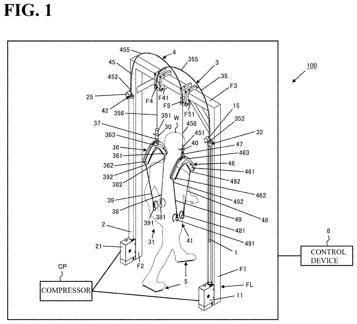
[0202]Next, working examples will be described. A body weight unloading apparatus having a similar configuration to the present embodiment was produced, and gait practice training was carried out on a treadmill with a hemiplegic patient.

first working example

[0203]In the first embodiment, the proximal ends of the support members were fitted to a test subject whose left leg was paralyzed and whose right leg was unaffected, and gait practice training was carried out while partially unloading the body weight of the test subject, with a similar processing procedure to the above embodiment. The total value of the unloading forces on the legs was set to a constant value (constant value set one of 7.5%, 10% or 15% of body weight; different depending on the conditions). The unloading force (unloading amount) acting on each leg was adjusted, by changing the constant terms of Formula 4. The walking speed of the treadmill was adjusted to a speed at which the test subject could walk comfortably in a range of 1 km / h to 2 km / h. While training was being implemented, the standing time on the unaffected side (right leg) and the standing time on the paralyzed side (left leg) were each measured, and the ratio of the standing time on the paralyzed side to ...

second working example and reference example

[0205]In a second working example and a reference example, similarly to the first embodiment, the proximal ends of the support members were fitted to a test subject whose left leg was paralyzed and whose right leg was unaffected, and gait practice training was carried out on a treadmill while partially unloading the body weight of the test subject with a similar processing procedure to the above embodiment. With the second embodiment and the reference example, five trials were carried out. As a common condition for the five trials, the total value of the unloading force on the legs was set to a constant value (15% of body weight).

[0206]In the first trial, as a reference example, the method of determining the unloading forces was changed, and the unloading force on each leg was set to the same constant value. On the other hand, in the second to fifth trials, as working examples, the unloading forces were determined similarly to the above embodiment. In the second trial, the values of...


PUM


Abstract

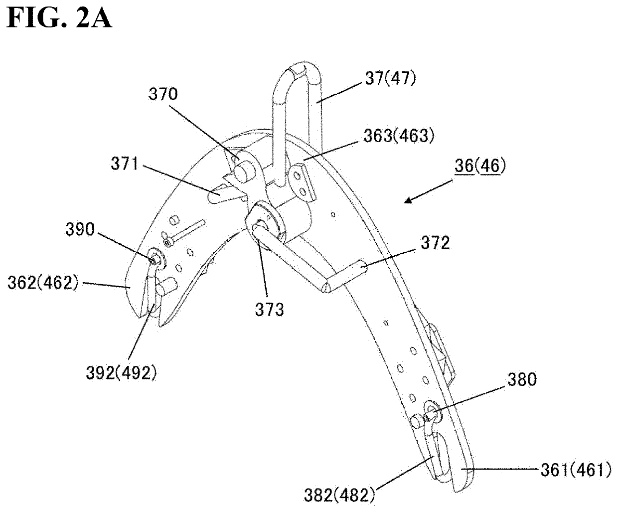
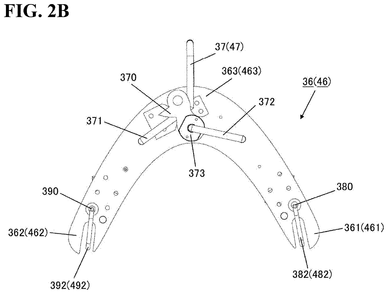
A body weight unloading apparatus according to an aspect of the present invention includes a first actuator, a second actuator, a first support member, a second support member, a sensor for measuring the imbalance between floor reaction forces respectively acting on the legs of a user, and a control device for controlling operations of the actuators. One end of the support members is respectively connected to the actuators, and the other end of the support members is fitted to the user such that unloading forces that are supplied by the actuators respectively act on the legs of the user. The control device controls the actuators so as to respectively generate unloading forces determined according to the imbalance between the floor reaction forces.

Description

TECHNICAL FIELD[0001]The present invention relates to a body weight unloading apparatus.BACKGROUND ART[0002]In order to restore the walking ability of individuals with gait impairments such as hemiplegic patients and elderly people who have difficulty walking on their own, for example, training programs for spontaneously generating a natural walking movement may be implemented. However, subjects who practice this walking movement fundamentally have difficulty supporting their weight on their own. As an example, hemiplegic patients have difficulty supporting the weight on their paralyzed side on their own. Thus, an apparatus (body weight unloading apparatus) configured to at least partially unload the body weight of the subject is utilized so that the subject can walk safely. For example, in clinical settings, a body weight unloading apparatus (body weight load reduction device) that lifts the body up vertically to support the body weight is used with subjects who walk on a treadmill...

Claims


Application Information

Patent Timeline
Patent Type & Authority Applications(United States)
IPC IPC(8): A61H3/00
CPCA61H3/008A61H2201/5061A61H2201/5007A61H2201/14A61H2201/1238A61H2201/1652A61H2201/149A61H2230/625
Inventor NODA, TOMOYUKITERAMAE, TATSUYATAKAI, ASUKAFURUKAWA, JUNICHIROMORIMOTO, JUNNAKANO, NAO
Owner ATR ADVANCED TELECOMM RES INST INT
Why Eureka
Try Eureka