Fan shroud and blower device
a technology of fan shroud and blower, which is applied in the direction of machines/engines, transportation and packaging, liquid fuel engines, etc., can solve the problems of unsatisfactory passing of traveling wind through the blower device, and the air volume performance of the blower device may deteriorate, so as to prevent the wind from flowing back, prevent the air volume performance from deteriorating, and improve the passing of traveling wind
- Summary
- Abstract
- Description
- Claims
- Application Information
AI Technical Summary
Benefits of technology
Problems solved by technology
Method used
Image
Examples
first modification example
[0068]
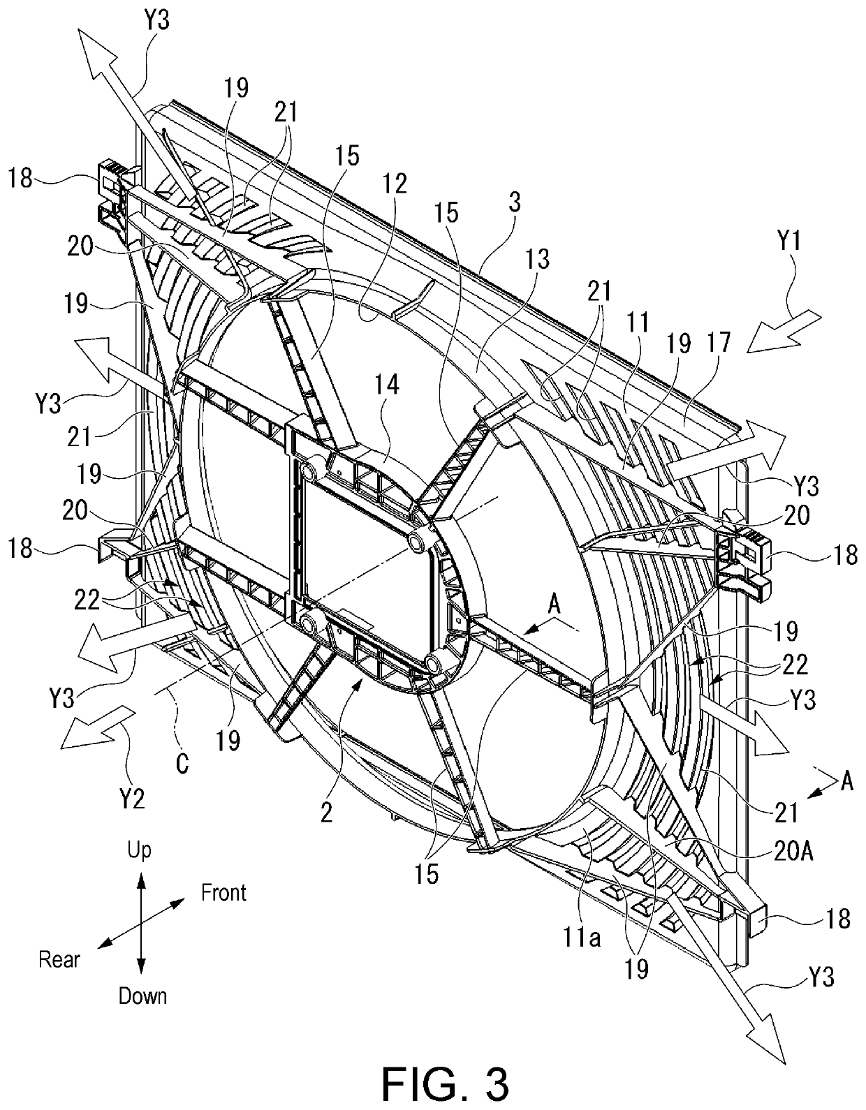
[0069]FIG. 9 is a perspective view of a fan shroud 4 in a first modification example as viewed from the rear side. FIG. 9 corresponds to FIG. 3 described above.
[0070]As shown in FIG. 9, a ventilation opening 21 may be formed in a long slit shape in the vehicle width direction. In this case, a plurality of ventilation openings 21 are arranged side by side in the up-down direction. Herein, a deflection louver 22 is formed in the ventilation openings 21 arranged in the upper half among the ventilation openings 21 so that the wind direction after passing through the ventilation opening 21 turns to an upward direction. On the other hand, a deflection louver 22 is formed in the ventilation openings 21 arranged in the lower half among the ventilation openings 21 so that the wind direction after passing through the ventilation opening 21 turns to a downward direction.
[0071]Even in the case of such a configuration, the same effects as those of the above embodiment can be obtained. Furt...
second modification example
[0072]
[0073]FIG. 10 is a perspective view of a fan shroud 4 in a second modification example as viewed from the rear side. FIG. 10 corresponds to FIG. 3 described above.
[0074]As shown in FIG. 10, a ventilation opening 21 may be formed in a long slit shape in the up-down direction. In this case, a plurality of ventilation openings 21 are arranged side by side in the vehicle width direction. In such a configuration, the wind after passing through the ventilation opening 21 goes toward the vehicle width direction outer side.
[0075]Therefore, according to the second modification example above, the same effects as those of the above embodiment can be obtained. Further, it is possible to increase the variation in the direction of the wind passing through the ventilation opening 21 due to the deflection louver 22.
third modification example
[0076]Further, in the above embodiment, it has been described that the deflection louver 22 includes the inclined wall 23 protruding toward the front side (one side in the normal direction) from the shroud wall surface 11, the lateral wall 24 bent and extended toward the vehicle width direction inner side from the front end of the inclined wall 23, and the vertical wall 25 which closes a space between two ends of the lateral wall 24 in the long-side direction and the shroud wall surface 11. Furthermore, it has been described that the inclined wall 23 extends obliquely with respect to the normal direction of the shroud wall surface 11 (with respect to the plane direction) so as to gradually extend toward the vehicle width direction inner side from the shroud wall surface 11 toward the front side. However, the disclosure is not limited thereto, and the inclined wall 23 may protrude toward the rear side from the shroud wall surface 11.
[0077]In this case, the inclined wall 23 gradually ...
PUM
 Abstract
Description
Claims
Application Information
 - R&D
- Intellectual Property
- Life Sciences
- Materials
- Tech Scout
- Unparalleled Data Quality
- Higher Quality Content
- 60% Fewer Hallucinations
Browse by: Latest US Patents, China's latest patents, Technical Efficacy Thesaurus, Application Domain, Technology Topic, Popular Technical Reports.
© 2025 PatSnap. All rights reserved.Legal|Privacy policy|Modern Slavery Act Transparency Statement|Sitemap|About US| Contact US: help@patsnap.com


