Filter apparatus

a filter element and filter element technology, applied in the field of filter element filters, can solve the problems of not being able to achieve the known solution and leaving much to be desired

Active Publication Date: 2011-11-01
HYDAC PROCESS TECH
View PDF26 Cites 0 Cited by
  • Summary
  • Abstract
  • Description
  • Claims
  • Application Information

AI Technical Summary

Benefits of technology

[0008]This object is basically achieved by a filter apparatus where the filter housing has a swirl space such that the fluid stream to be filtered is routed at least partially around the filter element in a swirling flow. For actual filtration operation, the properties of the cyclone are used in so far as the swirl space of the filter housing causes repeated deflection of the direction of motion of the fluid to be filtered. The associated swirling flow is able to be established along the entire filter surface of the filter element, with the result that the fluid stream to be filtered passes through the filter element to an increased degree and with high energy input, with simultaneous retention or separation of impurities. The swirling flow achieved in the filter housing caused by the action of the swirl space yields a laminar, helix-like fluid flow. In contrast to the otherwise conventional radial throughflow of a filter element transversely to its longitudinal axis, the filter apparatus of the invention leads to improved filtration performance and results. In this way, an increased throughput rate of the fluid to be filtered through the filter element can be achieved.
[0009]In one preferred embodiment of the filter apparatus according to the invention, the swirl space is formed by a conical widening of the filter housing in the direction of its one housing end. The feed inlet for the unfiltered medium extends through the filter housing off-center to the longitudinal axis of the filter element. This off-center feed causes improved generation of a cyclone-like flow under the action of the swirl space in the filter housing.
[0010]The conical widening of the filter housing in the region of the swirl space preferably undergoes transition into a cylindrical housing part or into one with a small conical tilt, with the result that partial damping of the swirl-like fluid flow occurs with reduced wall distances between the outside of the filter element and the inside of the filter housing. A kind of forced guidance for the purpose of a compressed fluid flow then results to increase the feed amount of fouled fluid for the filter element in this way.
[0011]In another preferred embodiment of the filter apparatus according to the invention, with a definable axial distance above on the free end of the filter element, a collecting space adjoins likewise contributing to making the fluid flow uniform in the upper region, and helping prevent supercritical turbulences within the fluid flow. This supercritical turbulence otherwise could adversely affect the filtration performance of the filter apparatus.

Problems solved by technology

Filtration by a filter element is not possible with the known solution.
The filtration line of these known solutions still leaves much to be desired.

Method used


Image

  • Filter apparatus
  • Filter apparatus
  • Filter apparatus

Examples


Embodiment Construction

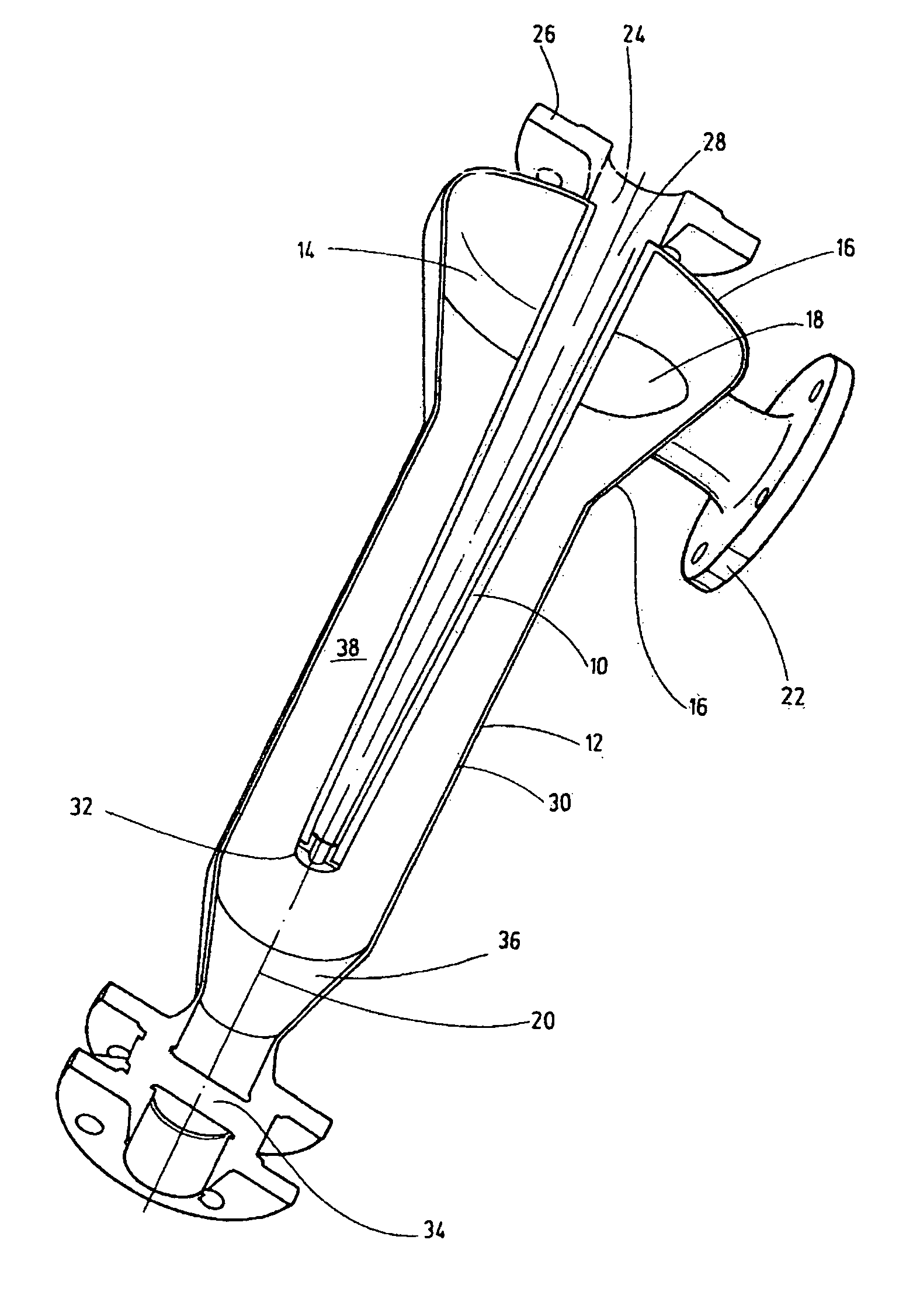
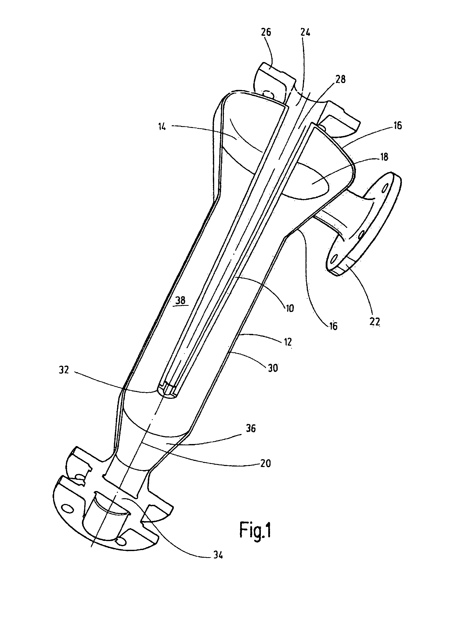
[0017]The filter apparatus according to the invention is used to separate impurities from a fluid stream, for example formed by a hydraulic medium. Fundamentally, the filter apparatus can also be used for gaseous media, aerosols, etc., which likewise form fluids. FIGS. 1 and 2 correspond to the conventional installation direction. To the extent the terms “top” and “bottom” are used below in this respect, they relate to the representations of the operating situation of the filter apparatus as shown in FIGS. 1 and 2.

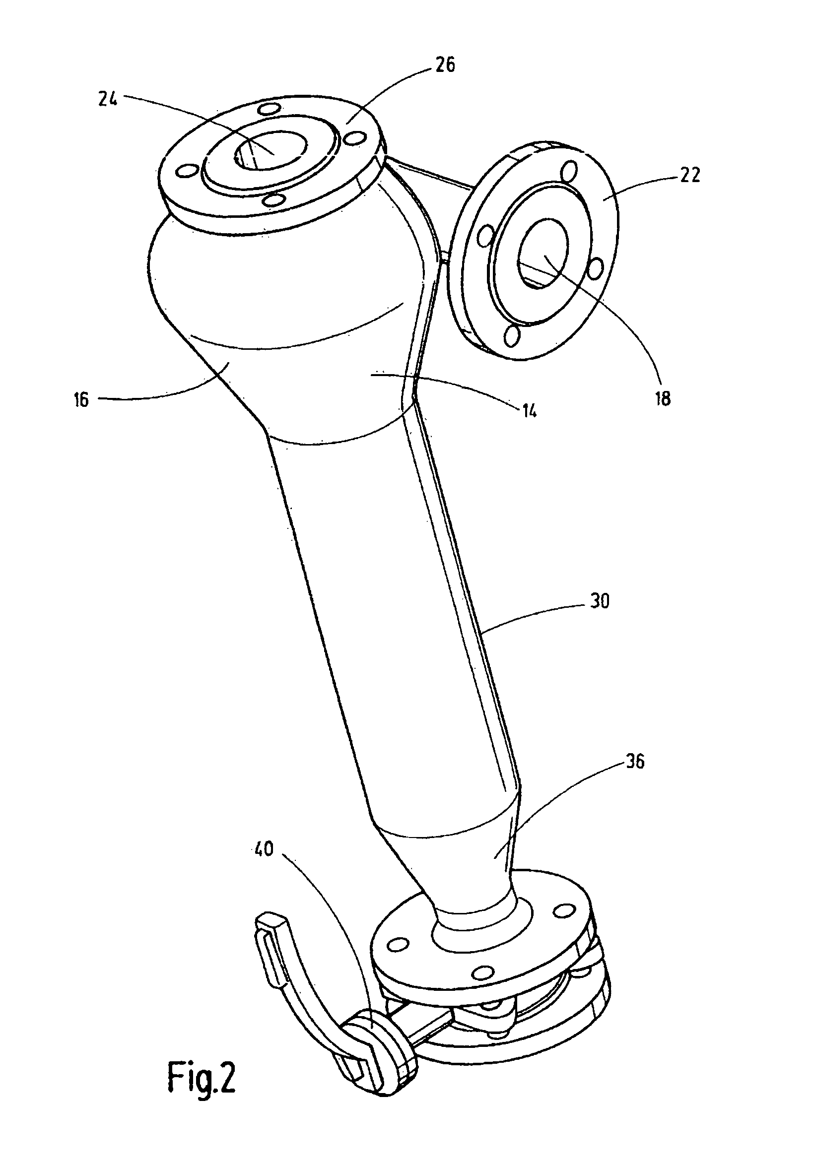
[0018]The filter element 10 shown in FIG. 1 is accommodated by a filter housing 12 of the filter apparatus. The filter housing 12 on its top end has a swirl space 14 used to route the fluid to be filtered at least partially in a swirling flow or cyclone flow around the filter element 10. In the illustrated solution, the swirl space 14 is formed by a conical widening of the filter housing 12 in the direction of its top end 16. Instead of this conical widening produced by th...


PUM

PropertyMeasurementUnit
axial distanceaaaaaaaaaa
lengthaaaaaaaaaa
centrifugal forceaaaaaaaaaa

Abstract

A filter apparatus deposits impurities from a fluid stream by use of a filter element (10) accommodated in a filter casing (12). The filter casing (12) has a swirl space (14) such that the fluid stream to be filtered is conducted at least partly in a swirling flow around the filter element (10). The properties of a cyclone are utilized for the actual filtration operation to the extent that the swirl space of the filter casing brings about multiple deflection of the direction of motion of the fluid to be filtered.

Description

FIELD OF THE INVENTION[0001]The invention relates to a filter apparatus for separating impurities from a fluid stream by using a filter element accommodated in a filter housing.BACKGROUND OF THE INVENTION[0002]Similar hydraulic filters and filter apparatus are readily available on the market in a plurality of embodiments (e.g., DE 197 11 589 A1). In addition to suction filter apparatus, filter apparatus as return line filters, in-line filters, or ventilation filters are known. In generic terms they are often referred to as hydraulic filters. Generally, these hydraulic filters are devices for separation of solids, with fibrous, grainy, or lattice-shaped filter media being used to separate solids from liquids or for separating dusts from gases.[0003]Furthermore, other separation devices in the prior art (e.g., DE 42 14 324 A1) are cyclones which are devices with which the action of a centrifugal force separates particles of solids from gases or liquids which are subsumed in the jargon...

Claims


Application Information

Patent Timeline
Patent Type & Authority Patents(United States)
IPC IPC(8): B01D50/00
CPCB01D29/114B01D29/48B01D29/908B01D29/94B01D2201/02B01D29/90B01D35/30
Inventor SCHNEIDER, THOMASWNUK, RALF
Owner HYDAC PROCESS TECH
Why Eureka
Try Eureka