Connector and connector assembly

a technology of connectors and connector parts, applied in the direction of coupling contact members, coupling device connections, securing/insulating coupling contact members, etc., can solve the problems of inability to meet the demands of compact and low profile of connectors, inability to suitably absorb misalignment in multiple directions, and insufficient adaptability of conventional connectors to the miniaturization of components and multipolarity of signals

Pending Publication Date: 2022-08-04
MOLEX INC
View PDF0 Cites 0 Cited by
  • Summary
  • Abstract
  • Description
  • Claims
  • Application Information

AI Technical Summary

Problems solved by technology

However, the conventional connectors are not sufficiently suited to the miniaturization of components and multipolarity of signals in recent electronic devices.
However, the terminal 851 for conventional connectors as described above is large, and not able to mee...

Method used


Image

  • Connector and connector assembly
  • Connector and connector assembly
  • Connector and connector assembly

Examples


Embodiment Construction

[0032]Embodiments will hereinafter be described in detail with reference to the drawings.

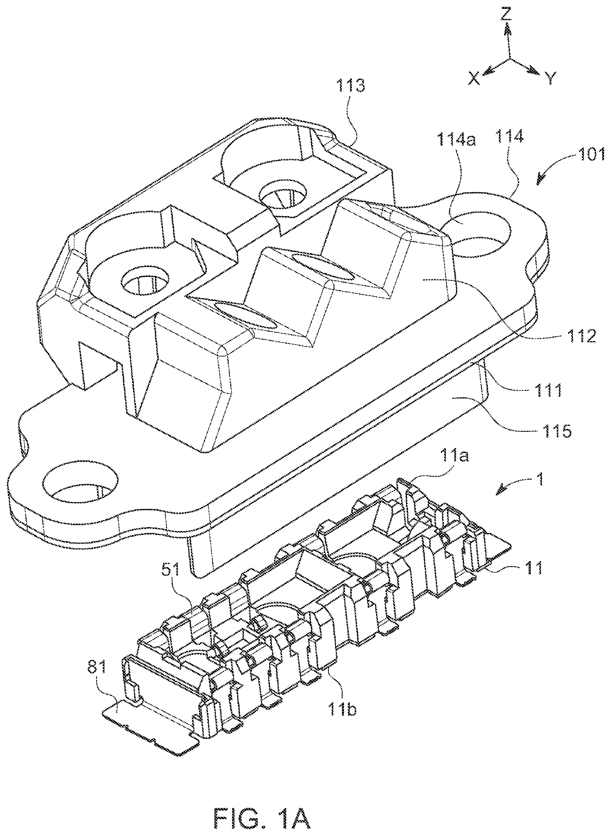
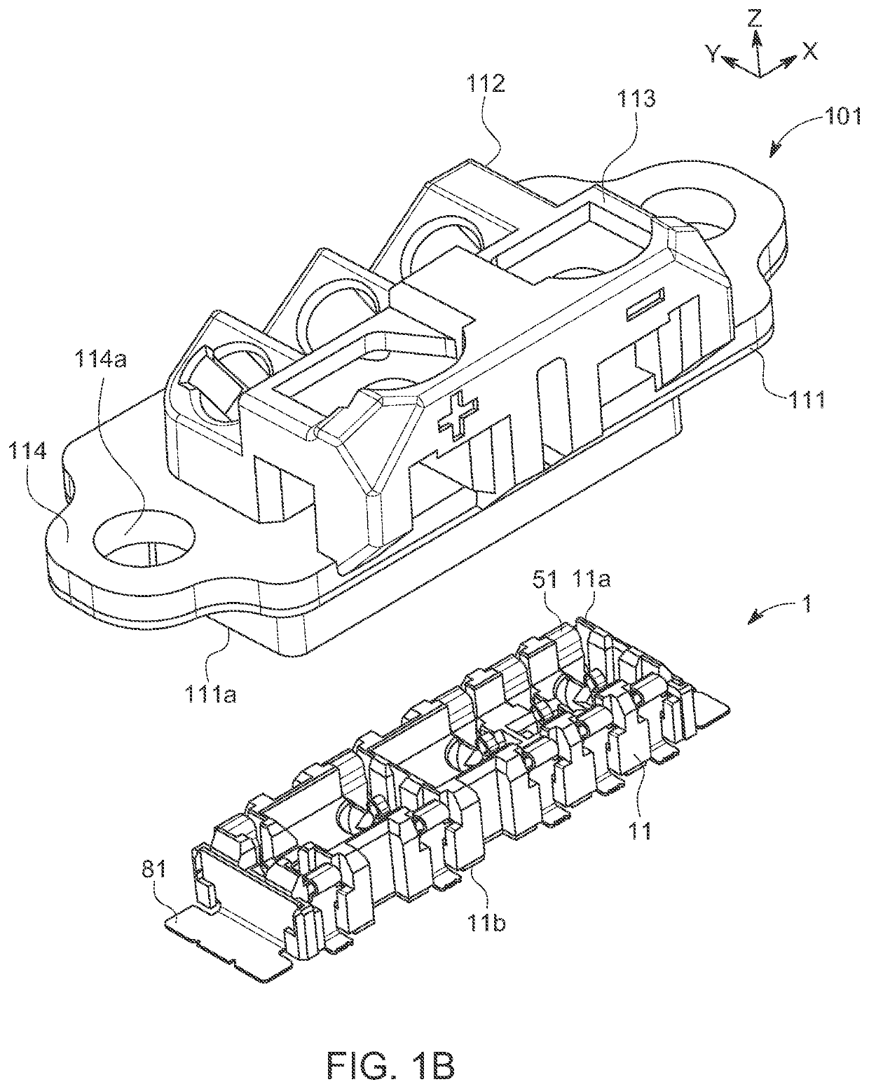
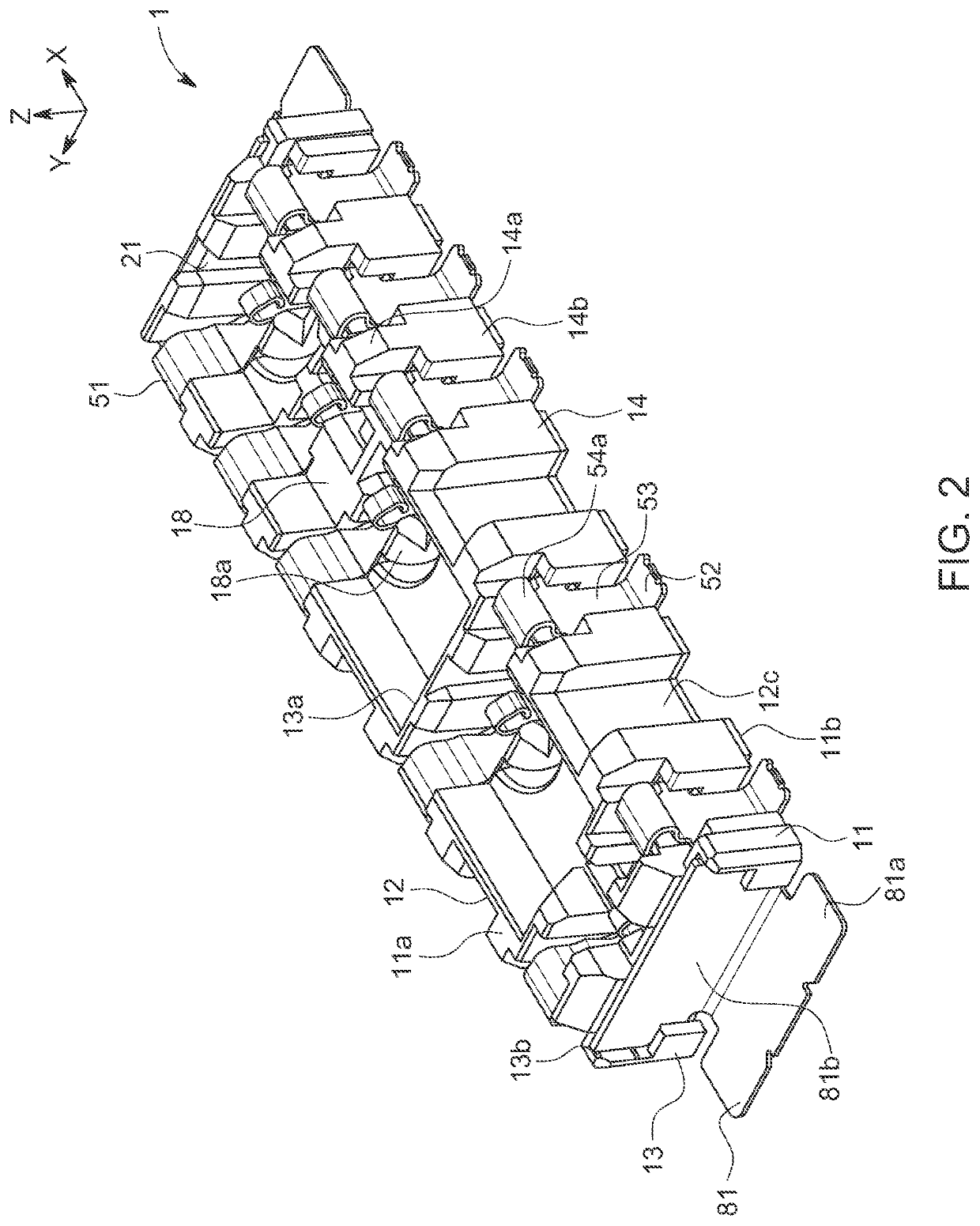
[0033]FIGS. 1A and 1B are perspective views seen from the side of the second connector illustrating the positional relationship between the first connector and the second connector according to the present embodiment before mating. FIG. 2 is a perspective view of the first connector according to the present embodiment. FIG. 3 is an exploded view of the first connector according to the present embodiment. FIGS. 4A-4C are three view drawings of the first connector according to the present embodiment. FIGS. 5A-5C are three view drawings of the first housing according to the present embodiment. FIG. 6 is a cross sectional perspective view of the essential parts of the first connector according to the present embodiment. Note that in FIGS. 1A and 1B, FIG. 1A is an oblique view from the front and FIG. 1B is an oblique view from the rear. In FIGS. 4A-4C, FIG. 4A is a plan view, FIG. 4B is a cross secti...


PUM


Abstract

A terminal including a main body part retained by a connector main body and a contact part connected to the upper end of the main body part and the free end of which can be connected to a counterpart terminal of a counterpart connector. The contact part including a connector base connected to the upper end of the main body part, a spring arm connected to the tip of the connector base and bent in a substantially s-shape, and a contact flexure part formed near the free end of the spring arm. The connector main body including a pair of side wall parts that extend in the longitudinal direction thereof and that retain the main body part. The connector base including an outward expanding part that bulges outward from the upper end of the main body part toward the connector main body and straddling the side wall parts without making contact with the side wall parts.

Description

RELATED APPLICATION[0001]This application claims priority to Japanese Application Serial No. 2019-187288, filed on Oct. 11, 2019, which is incorporated by reference in its entirety.TECHNICAL FIELD[0002]The present disclosure relates to a connector and a connector assembly.BACKGROUND ART[0003]Conventionally, with a substrate connector mounted on a substrate, technology using a terminal with a structure enabling absorbing misalignment through elastic deformation has been proposed for absorbing misalignment with a counterpart connector (for example, see patent reference 1).[0004]FIG. 12 is a perspective view illustrating a conventional connector terminal.[0005]In the diagram, 851 is a terminal of a board connector not shown that is mounted on the surface of a circuit board 901. This terminal 851 is fabricated by punching and bending a metal plate, made up of a flat plate main body 852 extending in a vertical direction relative to the surface of the circuit board 901, a pair of left and...

Claims


Application Information

Patent Timeline
IPC IPC(8): H01R12/71H01R12/91H01R13/40H01R13/24
CPCH01R12/716H01R13/2407H01R13/40H01R12/91H01R13/41H01R13/2442H01R12/57
Inventor MIYAHARA, KENJITANAKA, MIKIJISHIMOYAMA, HIROSHINOGAWA, YOSHITERU
Owner MOLEX INC
Why Eureka
Try Eureka