Security devices and methods of manufacture thereof

a technology of security devices and micro-images, applied in the field of security devices, can solve the problems of affecting the viewer's ability to distinguish genuine from counterfeit devices, affecting the relative positioning of sampling elements and micro-images, and further exacerbated problems

Pending Publication Date: 2022-08-18
DE LA RUE INT LTD
View PDF8 Cites 0 Cited by
  • Summary
  • Abstract
  • Description
  • Claims
  • Application Information

AI Technical Summary

Benefits of technology

The patent text describes a method of forming a non-dispersive color-generating relief structure in a reflective sampling element. This structure improves the registration between the image elements and the reflective sampling elements, allowing for better alignment. Different reflective coatings can be applied to complete the structure, enhancing its reflectivity. The technical effect is an improved and reliable method for forming a high-quality and efficient reflective sampling element array.

Problems solved by technology

A problem with these known devices exists in that it is difficult to control the relative positioning of the sampling elements and the microimages.
This poses a problem for security since different authentic security devices can have significantly different appearances, which affects a viewer's ability to distinguish genuine from counterfeit devices.
The problem is further exacerbated when it is desired to use multiple colours in the security device.
It is very difficult to achieve register between different colours when using, for example, printing techniques to form the microimages since different colours are typically printed in separate print runs.
However, diffraction gratings exhibit diffractive dispersion, which means that they diffract white light incident along a single incidence direction into a range of angles in dependence on wavelength.

Method used


Image

  • Security devices and methods of manufacture thereof
  • Security devices and methods of manufacture thereof
  • Security devices and methods of manufacture thereof

Examples


Embodiment Construction

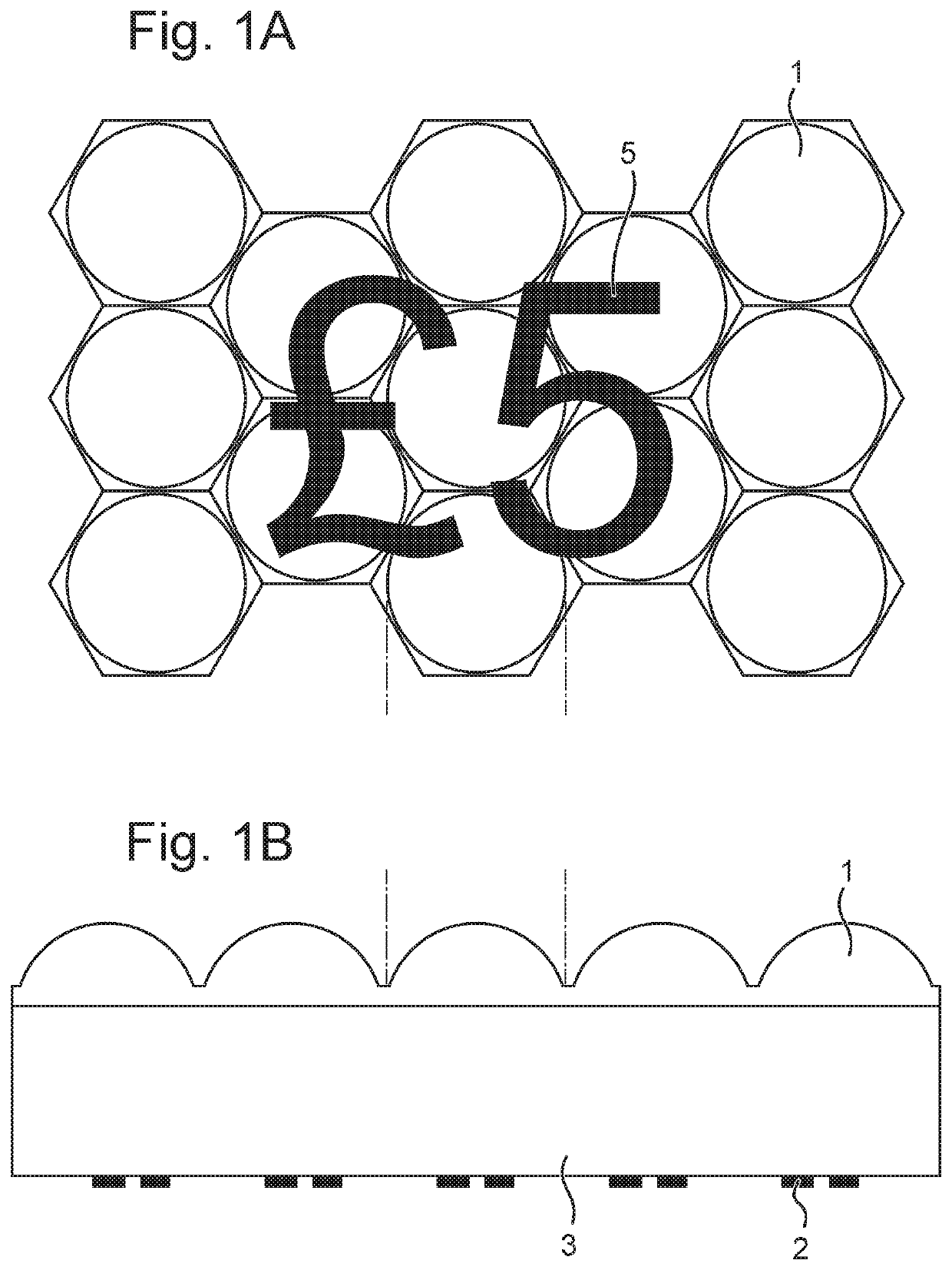
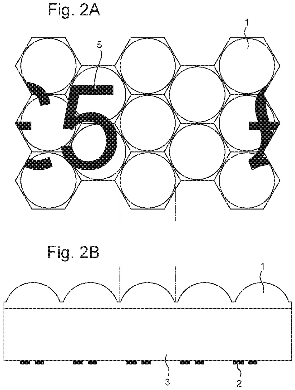
[0057]FIGS. 1A to 2B show known security devices that utilise sampling element arrays and image element arrays. These Figures demonstrate the problem that poor registration can pose.

[0058]FIG. 1A shows, in plan view, an array of sampling elements, in this case lenses 1. It will be appreciated that this view is schematic, showing only thirteen lenses, whereas in practice many more lenses would typically be used in a security device. FIG. 1B shows the security device in cross-sectional view and shows that the lenses 1 are spaced from an array of printed image elements 2 by an optical spacer layer 3. This is a conventional moiré magnification device, as described in EP 1695121 A, WO 94 / 27254 A, WO 2011 / 107782 A and WO 2011 / 107783 A, and each image element is a microimage, being a miniaturised version of the image to be displayed, in this case, the symbol “£5”.

[0059]The pitches of the sampling element array 1 and the image element array 2 are different from one another, such that each s...


PUM


Abstract

device includes an array of reflective sampling elements. A non-dispersive colour-generating relief structure is formed in a surface of the reflective sampling elements. The non-dispersive colour-generating relief structure defines an array of image elements across the array of reflective sampling elements. The array of image elements defined by the non-dispersive colour-generating relief structure and the array of reflective sampling elements cooperate to exhibit an optically variable effect.

Description

FIELD OF THE INVENTION[0001]The present invention relates to security devices such as those suitable for use in or on security documents such as banknotes, identity documents, passports, certificates and the like, as well as methods for manufacturing such security devicesDESCRIPTION OF THE RELATED ART[0002]To prevent counterfeiting and enable authenticity to be checked, security documents are typically provided with one or more security elements which are difficult or impossible to replicate accurately with commonly available means, particularly photocopiers, scanners or commercial printers.[0003]Many security devices rely on the interaction between an array of sampling elements, such as an array of microlenses or micromirrors, and an array of image elements, such as a printed array of microimages, to produce an optically variable effect.[0004]One class of such security devices is moiré magnifier devices (examples of which are described in EP 1695121 A, WO 94 / 27254 A, WO 2011 / 107782...

Claims


Application Information

Patent Timeline
IPC IPC(8): B42D25/324B42D25/328B42D25/342B42D25/373B42D25/425
CPCB42D25/324B42D25/328B42D25/425B42D25/373B42D25/342
Inventor HOLMES, BRIAN
Owner DE LA RUE INT LTD
Why Eureka
Try Eureka