Medium-voltage switchgear system having single phase breaker control

a switchgear and control technology, applied in the field of electric switchgear systems, can solve the problems of large current, deflected extension rails, cumbersome lifting trucks,

Active Publication Date: 2022-08-25
JST POWER EQUIP INC
View PDF13 Cites 7 Cited by
  • Summary
  • Abstract
  • Description
  • Claims
  • Application Information

AI Technical Summary

Problems solved by technology

The lift-truck may be cumbersome and the extension rails may deflect.
Short circuit events and similar overcurrent or other fault conditions may generate very large currents, which places physical stresses on the circuit breaker and the racking system that includes the truck that racks in and racks out the circuit breaker from the electrically connected, test, and disconnected positions.
Many switchgear systems include shutters that fail closed and cover primary circuit contacts, but sometimes cause sparks and burning.
In rare cases when they fail in a closed position, there may be an explosion.
High heat is often generated in these interior compartments, especially during a fault or short circuit event that creates arcing conditions.
In some cases, the buses are difficult to cool because the buses are sometimes aligned along a common X-axis in a vertically stacked arrangement, causing hot air from lower buses to heat up the upper buses.
These annular rings depending on their configuration may cause high electrostatic field stresses and shorter flash over path links to grounded objects in the switchgear system.
These high amperage circuit breakers and switchgear contact fingers are a source of heat and excess temperature rises may cause failures.

Method used


Image

  • Medium-voltage switchgear system having single phase breaker control
  • Medium-voltage switchgear system having single phase breaker control
  • Medium-voltage switchgear system having single phase breaker control

Examples


Embodiment Construction

[0047]Different embodiments will now be described more fully hereinafter with reference to the accompanying drawings, in which preferred embodiments are shown. Many different forms can be set forth and described embodiments should not be construed as limited to the embodiments set forth herein. Rather, these embodiments are provided so that this disclosure will be thorough and complete, and will fully convey the scope to those skilled in the art.

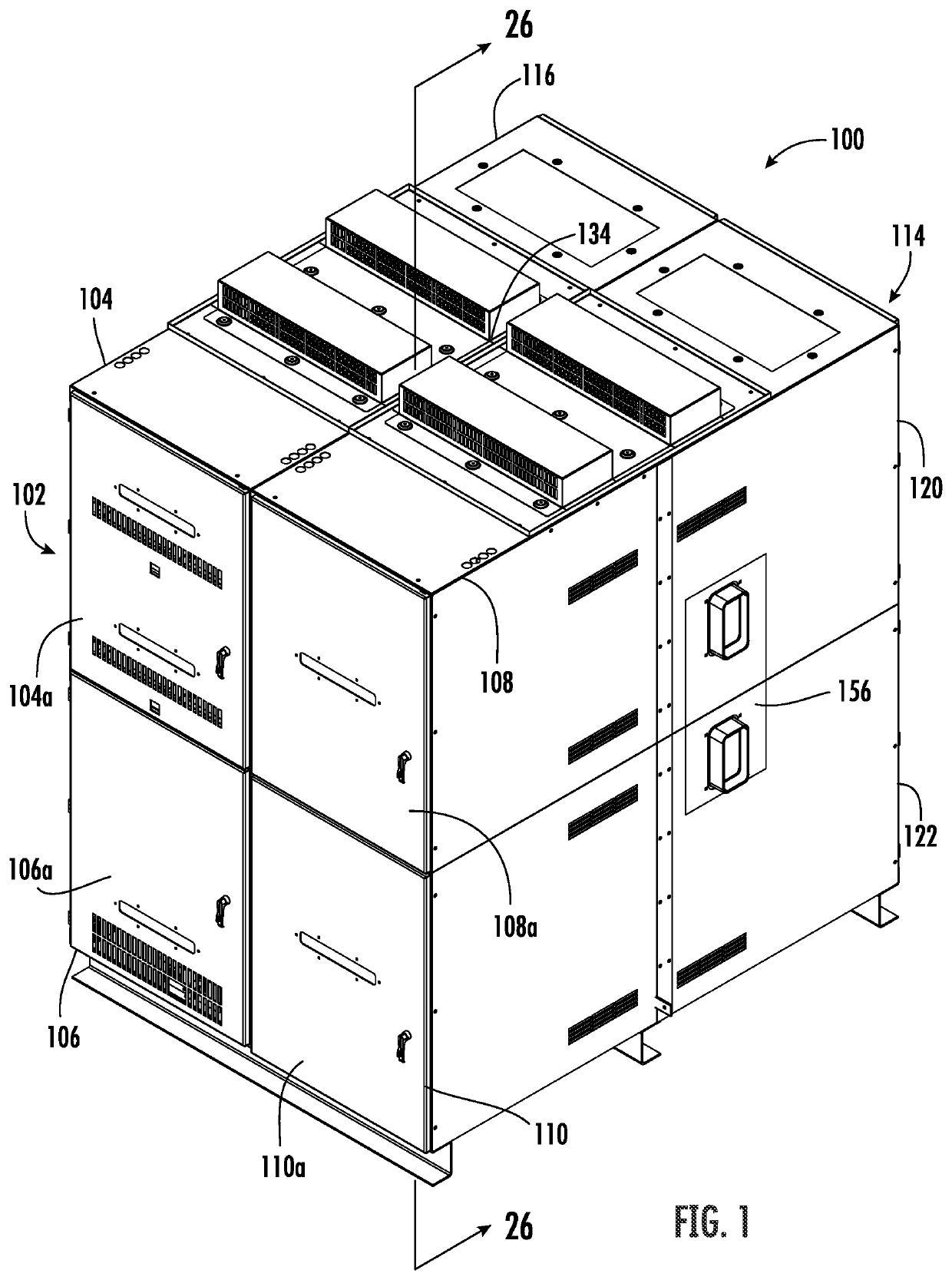
[0048]Referring now to FIG. 1, there is illustrated generally at 100 an electrical switchgear system in accordance with a non-limiting example that includes a front switchgear section 102 having first and second sets of front upper and lower switchgear housings 104, 106, 108, 110 and having joined sidewalls. Referring also to FIG. 1, and the more schematic representation of the switchgear system 100 shown in FIGS. 19-24, a rear switchgear section 114 includes first and second sets of rear upper and lower switchgear housings 116, 118, 120, 12...


PUM


Abstract

A medium-voltage switchgear system includes a three-phase circuit breaker having first, second and third single-phase vacuum interrupters connected between respective first, second and third single-phase inputs and first, second and third single-phase outputs. Magnetic actuators are connected to first, second and third single-phase vacuum interrupters, which are configured to receive an interrupt signal and in response, actuate the respective vacuum interrupter connected thereto into an open circuit condition. A controller circuit is connected to each of the first, second and third magnetic actuators and generates an interrupt signal in response to a detected single-phase overcurrent or fault on a single-phase circuit and interrupt that single-phase circuit on which the single-phase overcurrent or fault occurred and maintain power on the remaining two single-phase circuits over which a single-phase overcurrent or fault was not detected.

Description

PRIORITY APPLICATION(S)[0001]This application is based upon provisional application Ser. No. 63 / 153,419, filed Feb. 25, 2021, the disclosure which is hereby incorporated by reference in its entirety.FIELD OF THE INVENTION[0002]The present invention relates to electrical systems, and more particularly, to electrical switchgear systems.BACKGROUND OF THE INVENTION[0003]Metal-clad or metal-enclosed medium voltage switchgear systems operate as three-phase systems that connect to the three-phase power distribution grid and provide various control functions and provide protection against short circuit events and similar overcurrent or other fault conditions. These switchgear systems include transformers to reduce the primary circuit voltage, which can be greater than 1,000 volts, to a much lower voltage that may energize control circuits or monitor or meter the primary voltage. These switchgear systems and associated load circuits may be protected from damage by a fuse when the transformer...

Claims


Application Information

Patent Timeline
Patent Type & Authority Applications(United States)
IPC IPC(8): H02B11/173H02B1/38H02B1/32
CPCH02B11/173H02B1/38H02B1/32H02B1/56H02B11/04H02B11/26H02B11/127H02B11/24H01H33/022H01H33/6662H01H33/59H02B1/36H02B1/565H02B11/167
Inventor HANNA, ROBERT L.FISCHER-CARNE, PATRICK R.DAVIS, DANIEL C.ALVELO, JR., GUILLERMOPAWAR, RAHUL M.LIANG, HAONING
Owner JST POWER EQUIP INC
Why Eureka
Try Eureka