
Self-calibrating transmission line resonator oscillating driver apparatus

a technology of transmission line and driver, which is applied in the field of information handling system, can solve the problems of reducing broadcast efficiency, difficult to precisely match in real-time the frequency driven into the transmission line at the drifting frequency of the transmission line, and maintaining optimal resonance with the transmission lin

Active Publication Date: 2022-09-15
DELL PROD LP
View PDF6 Cites 0 Cited by
  • Summary
  • Abstract
  • Description
  • Claims
  • Application Information

AI Technical Summary

Benefits of technology

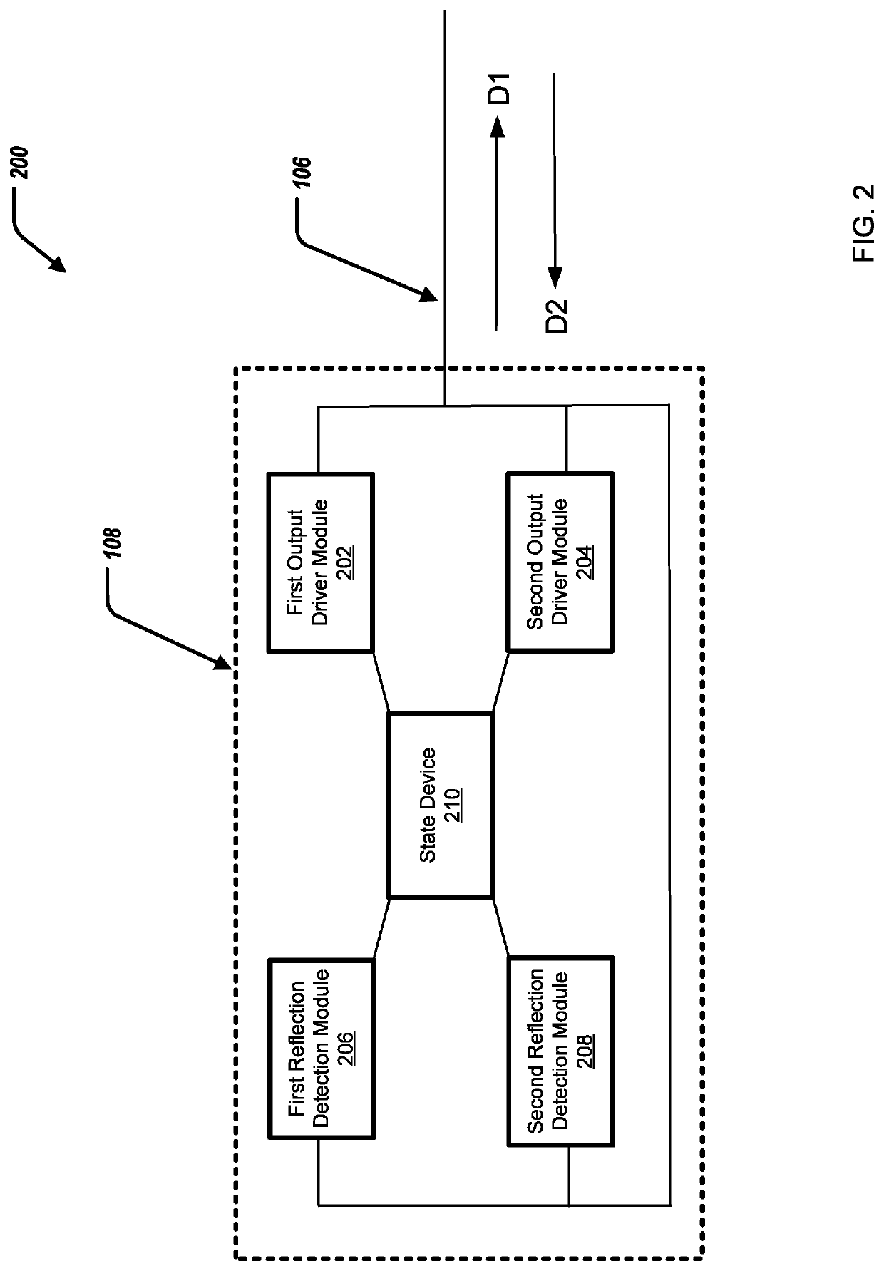
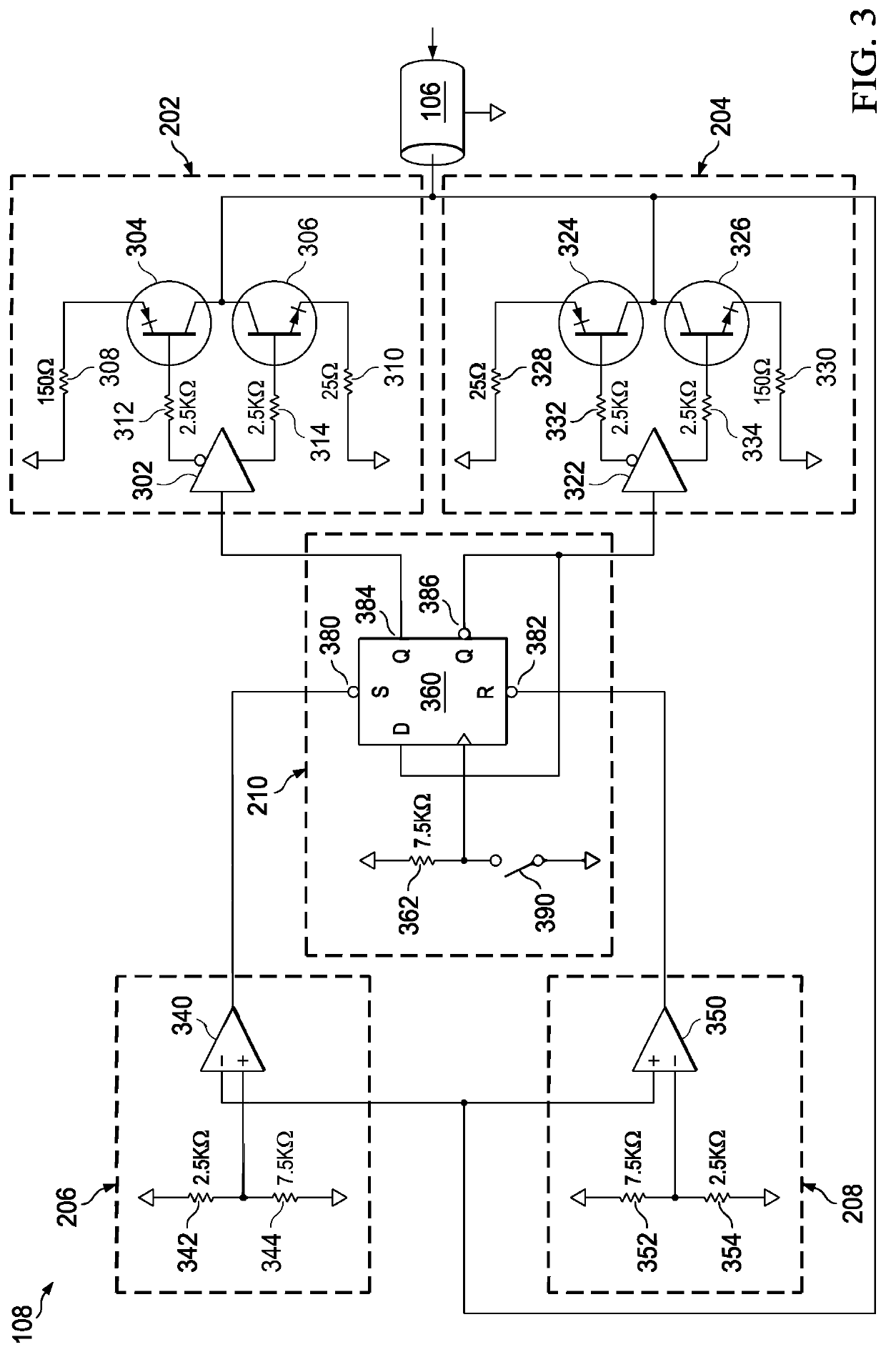
The patent describes a device that can detect and adjust the power of signals transmitted through a transmission line. The device includes two output drivers that transmit signals in opposite directions along the line. The device also includes a detection module that can detect the signals reflected from the line and adjust the power state of the output drivers accordingly. The technical effect of this device is that it can improve the stability and accuracy of signal transmission in a flexible and efficient way.

Problems solved by technology

Off-resonant variations in a frequency driven into a transmission line can cause reduced broadcast efficiency.
Dynamic real-time electrical characteristic variations of the transmission line (and transmission line resonator elements) make it difficult to precisely match in real-time the frequency driven into the transmission line at the drifting frequency of the transmission line.
However, neither of these approaches maintain optimal resonation with the transmission line, and are susceptible to real-time changes and variations in the transmission line electrical characteristics that can lead to a sub-optimal resonant frequency.

Method used


Image

  • Self-calibrating transmission line resonator oscillating driver apparatus
  • Self-calibrating transmission line resonator oscillating driver apparatus
  • Self-calibrating transmission line resonator oscillating driver apparatus

Examples


Embodiment Construction

)

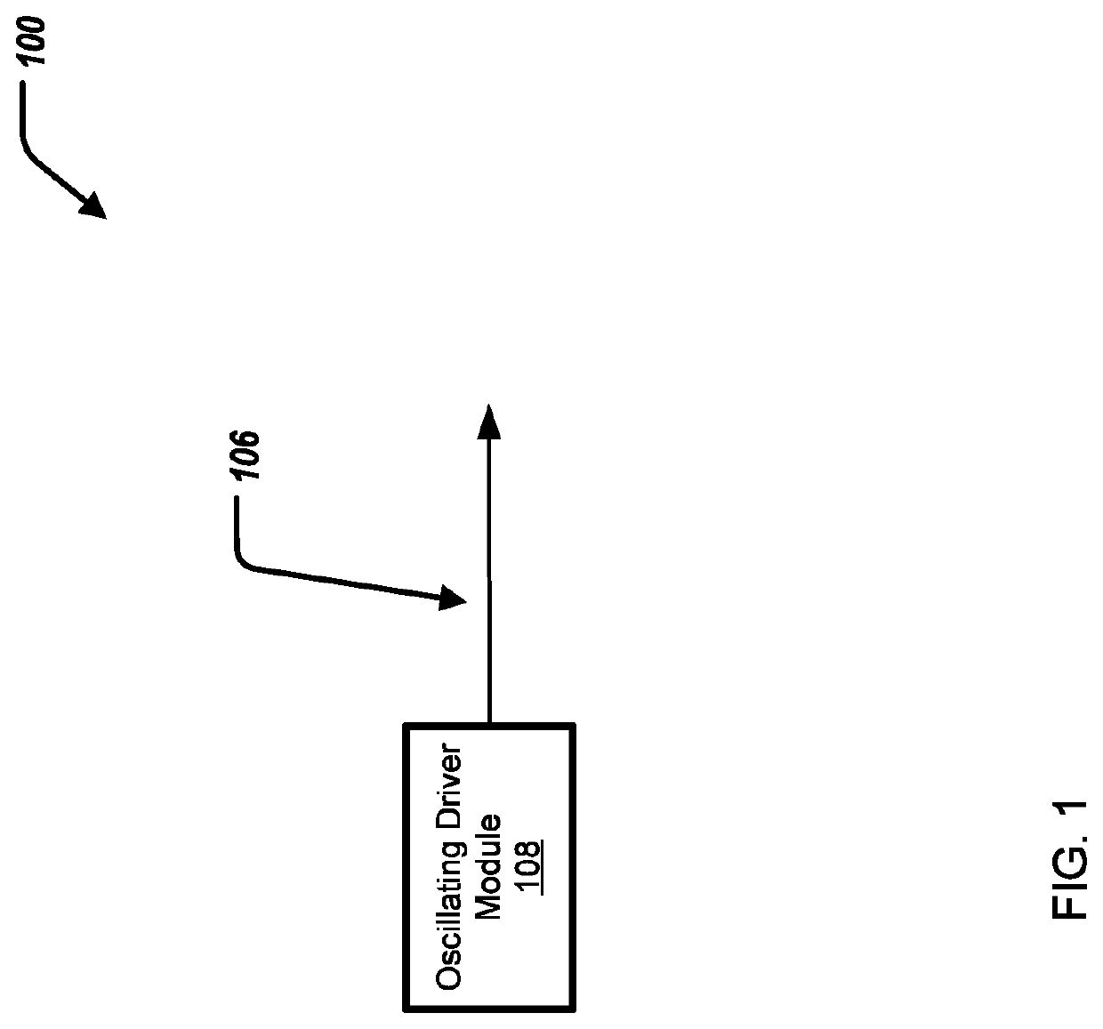
[0013]This disclosure discusses methods and systems for matching a resonant frequency of a transmission line. In short, an oscillating driver module can generate / drive a resonant frequency along a transmission line while optimizing broadcast power output and efficiency. The oscillating driver module can self-calibrate its output frequency to the resonant frequency of the transmission line. As a result, the variable factors for propagation velocity and delay due to variations in impedance are accounted for. Further, as the environment changes, the frequency driven by the oscillating driver module can change accordingly. Thus, the frequency that is driven by the oscillating driver module can match an optimal resonant frequency of the transmission line 106.

[0014]Specifically, this disclosure a self-calibrating transmission line resonator oscillating driver apparatus, including: a first output driver module configured to transmit a first forward signal of a first magnitude along a firs...


PUM


Abstract

A self-calibrating transmission line resonator oscillating driver apparatus, including: a first output driver module configured to transmit a first forward signal along a transmission line; a second output driver module configured to transmit a second forward signal along the transmission line; a first reflection detection module configured to detect a first return signal of the first forward signal reflected along the transmission line; and a second reflection detection module configured to detect a second return signal of the second forward signal reflected along the transmission line; wherein, when the first reflection detection module detects the first return signal of the first forward signal reflected along the second direction of the transmission line, providing a signal to i) change a power state of the first output driver module to an off-power state and to ii) change a power state of the second output driver module to an on-power state.

Description

BACKGROUNDField of the Disclosure[0001]The disclosure relates generally to an information handling system, and in particular, self-calibrating transmission line resonator oscillating driver apparatus.Description of the Related Art[0002]As the value and use of information continues to increase, individuals and businesses seek additional ways to process and store information. One option available to users is information handling systems. An information handling system generally processes, compiles, stores, and / or communicates information or data for business, personal, or other purposes thereby allowing users to take advantage of the value of the information. Because technology and information handling needs and requirements vary between different users or applications, information handling systems may also vary regarding what information is handled, how the information is handled, how much information is processed, stored, or communicated, and how quickly and efficiently the informat...

Claims


Application Information

Patent Timeline
IPC IPC(8): G01R27/06G01R27/26G01R27/32
CPCG01R27/06G01R27/2664G01R27/32H04B3/02H04B17/103H04B17/14H04B17/11
Inventor LASH, STEVEN JAY
Owner DELL PROD LP
Learn More